This Configuration Guide shows how to configure a GRE tunnel within an IPsec connection.
The description in this Configuration Guide follows a configuration in the new user interface (web interface) available from icom OS 5.5. Update your router to the latest version of icom OS for the required functionality of the new user interface. The description of this configuration in the classic web interface is available in this Configuration Guide.
Situation
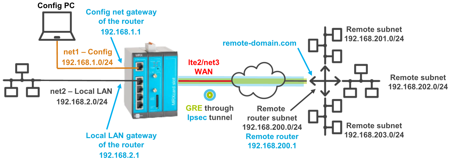
A remote router has several local subnets that need to be addressed from the INSYS router. An IPsec connection only allows to address one subnet. A GRE connection can be established to more than one subnet, but cannot be encrypted. To be able to establish encrypted connections to more than one subnet, it is possible to route a GRE tunnel through an encrypted IPsec connection.
Solution
It is prerequisite that you have access to the web interface of the router and the router is configured for a WAN connection using the startup wizard from default settings. It is also prerequisite that the remote router supports GRE via IPsec. The following figure shows the network topology that is used for this example:
|
|
Update your router to iom OS 7.3 or later first! All encryption algorithms that are no longer considered sufficiently secure have been removed starting with this version, which eliminates the possibility of such algorithms being used inadvertently. |
-
Open the user interface of the router in a browser: insys.icom [1]
-
Click on
 on the
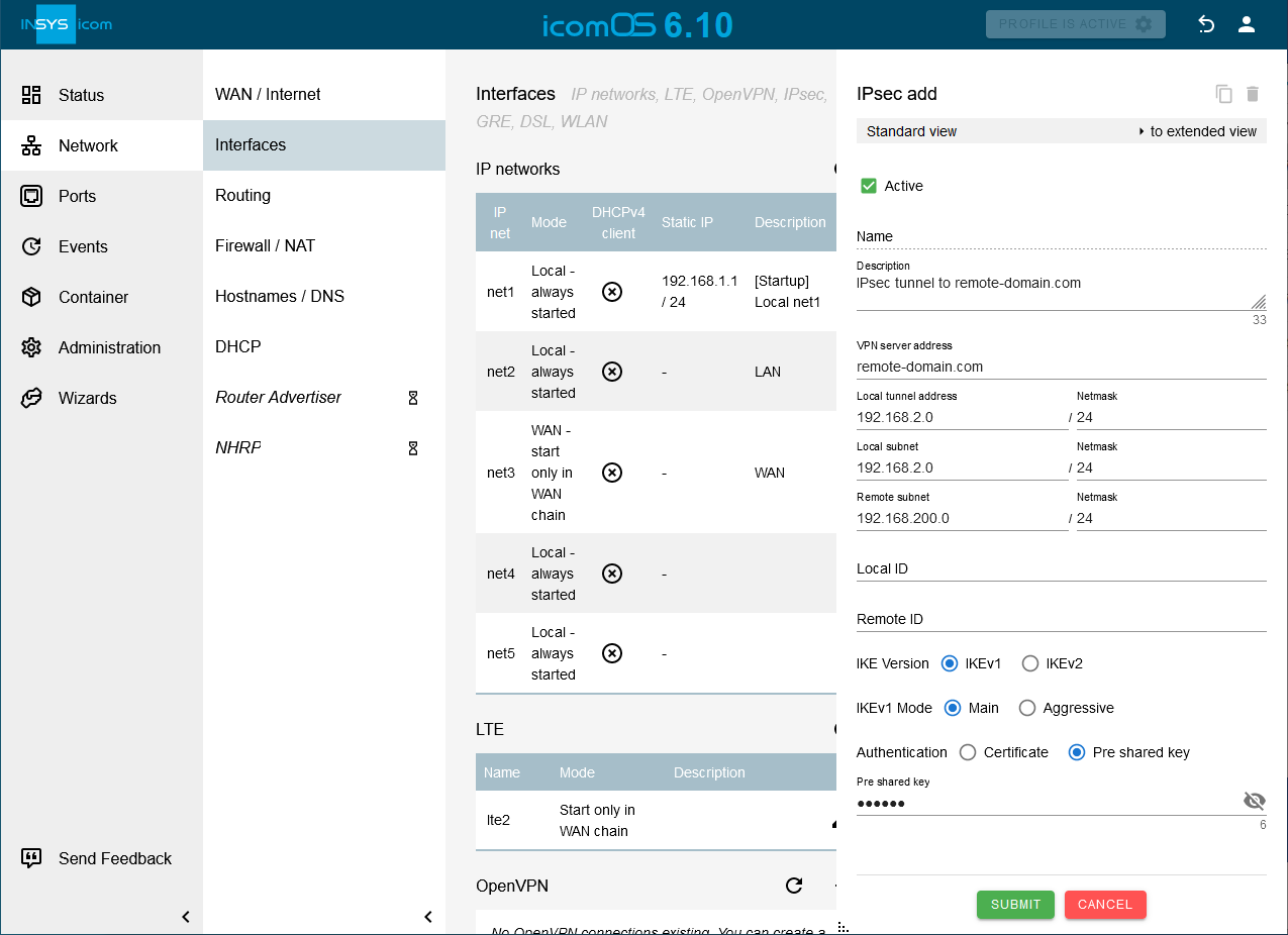
  Network → Interfaces page under IPsec to add a new IPsec tunnel and configure this accordingly: [2]
-
Description: IPsec tunnel to remote-domain.com
-
VPN server address: remote-domain.com
-
Local tunnel address: 192.168.2.0 / 24
-
Local subnet: 192.168.2.0 / 24
-
Remote subnet: 192.168.200.0 / 24
-
Configure authentication and encryption according to the settings of the remote router.
-
-
Click on SUBMIT .
-
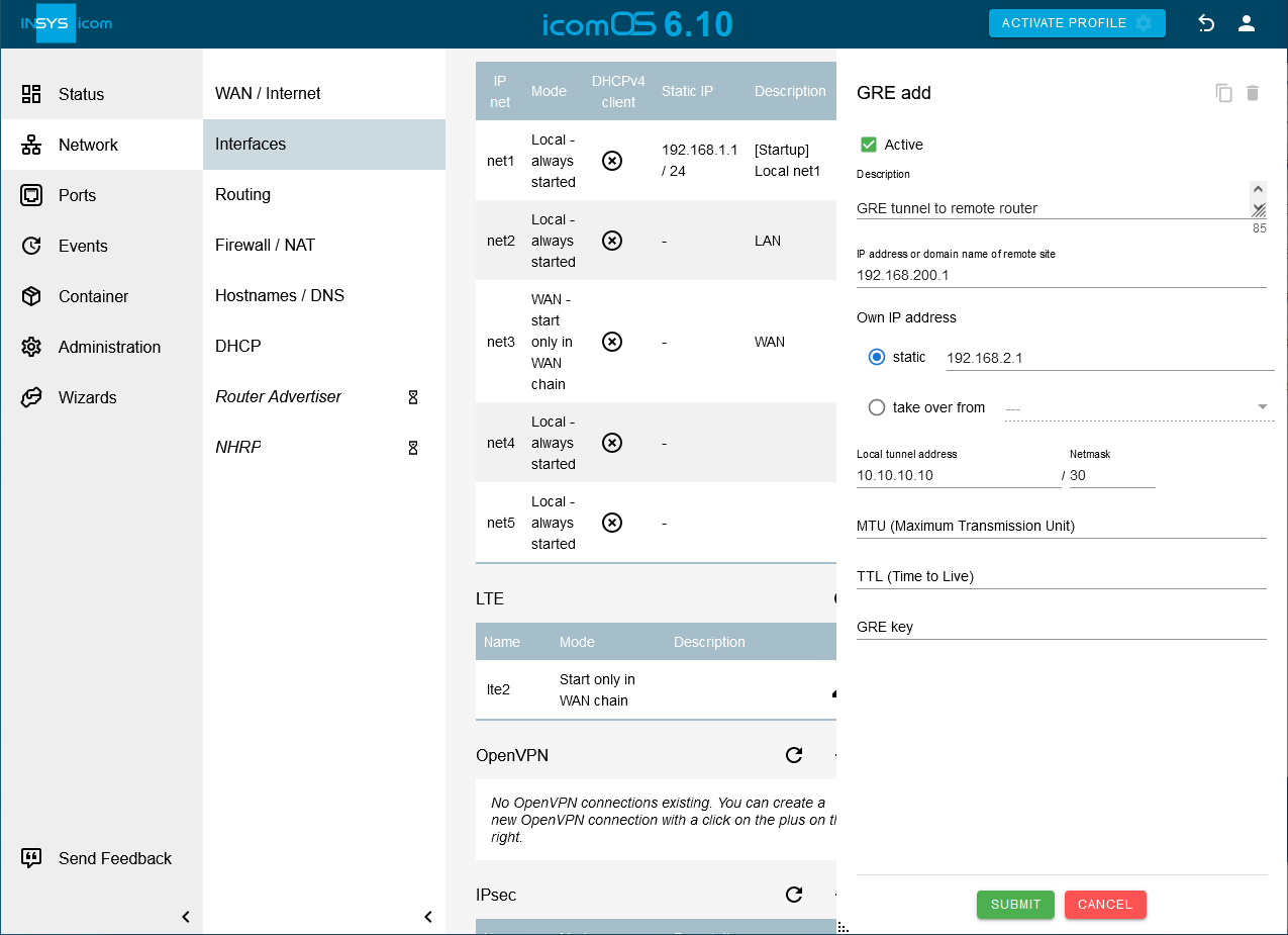
Click on
on the Network → Interfaces page under GRE to add a new GRE tunnel and configure this accordingly: [3] -
Click on SUBMIT .
-
Click on
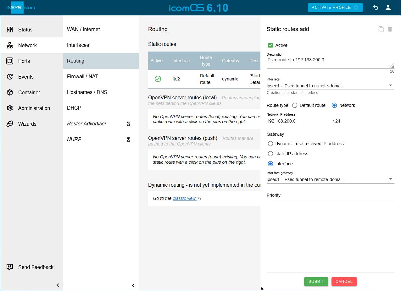
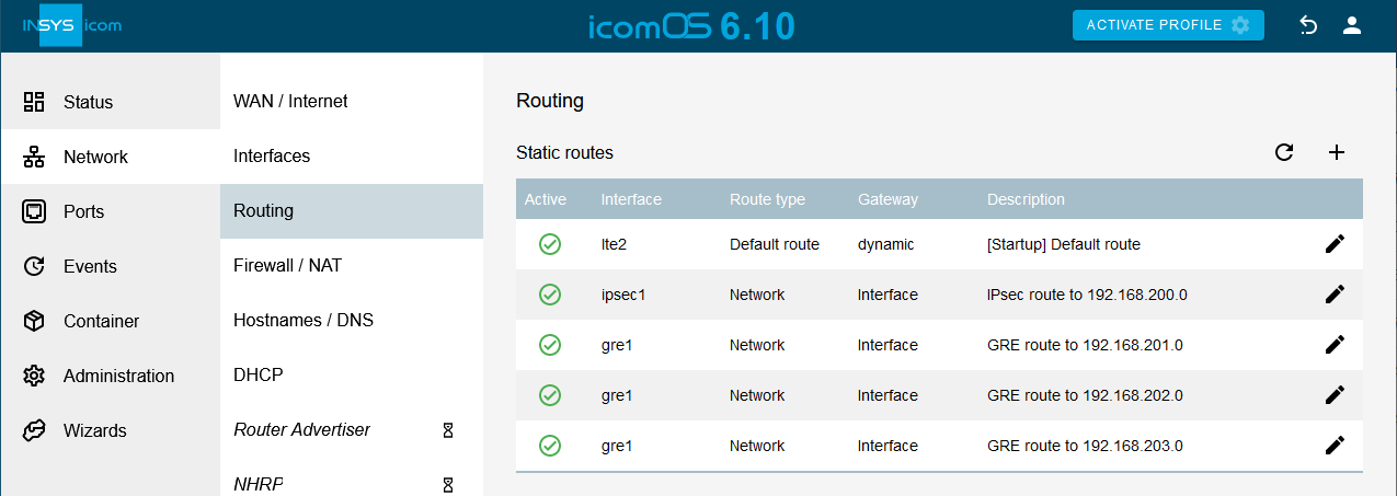
on the Network → Routing page under Static routes to add a new static route and configure this accordingly: [6]-
Description: IPsec route to 192.168.200.0
-
Creation after start of Interface: ipsec1
-
Type of the route: Network 192.168.200.0 / 24
-
Gateway: interface ipsec1
-
-
Click on SUBMIT .
-
Click on
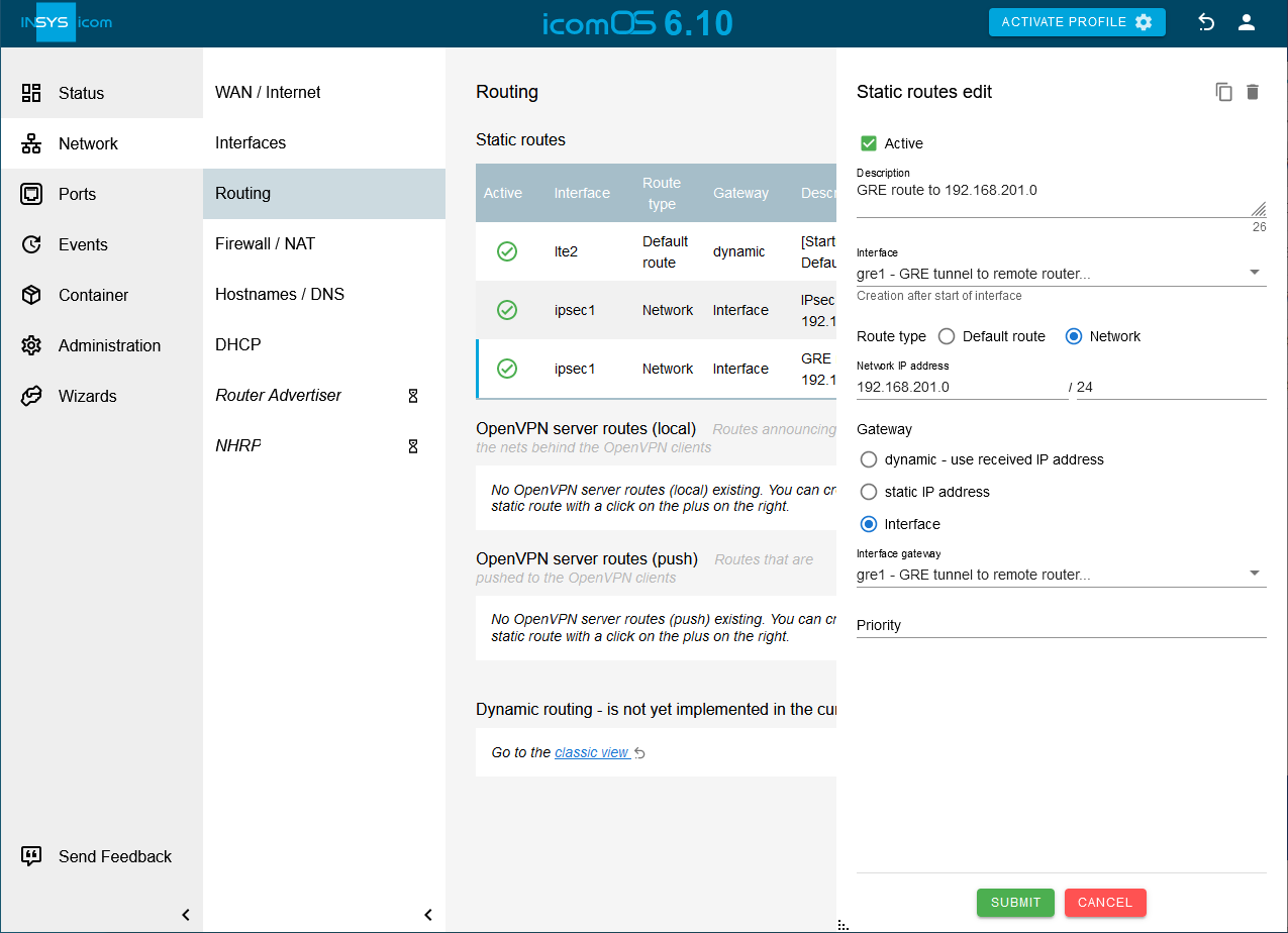
on the Network → Routing page under Static routes to add a new static route and configure this accordingly: [7]-
Description: GRE route to 192.168.201.0
-
Creation after start of interface: gre1
-
Type of the route: Network 192.168.201.0 / 24
-
Gateway: interface gre1
-
-
Click on Save settings.
-
Click on SUBMIT .
-
Add the next two routes to the remote subnets 192.168.202.0 and 192.168.203.0 accordingly.
-
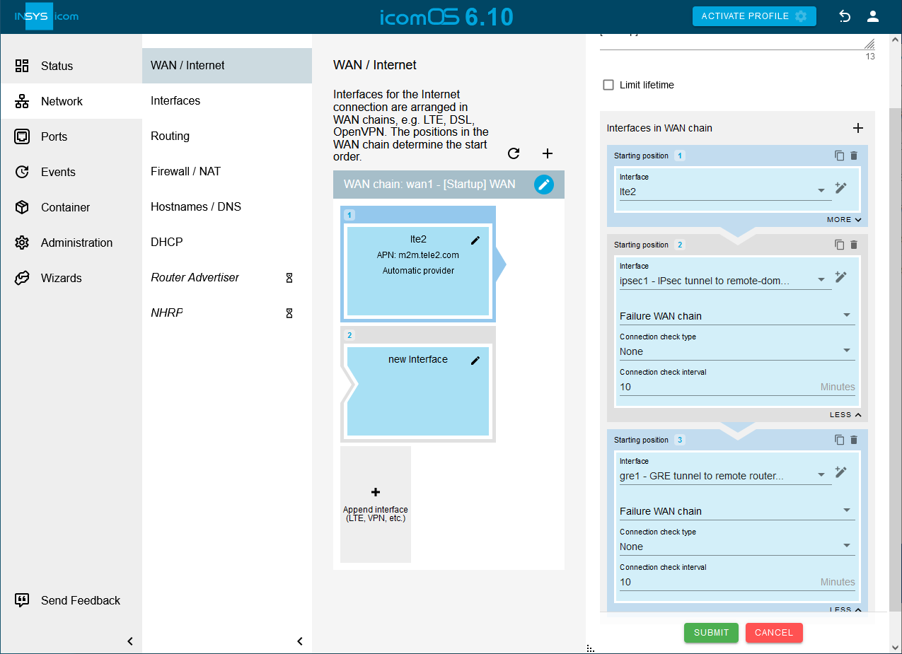
Click on
in the WAN chain added by the Startup wizard on the Network → WAN / Internet page to add another interface to the WAN chain. [8] -
Select for the interface on Starting position 2 the Interface ipsec1.
-
Click on
again to add another interface to the WAN chain. -
Select for the interface on Starting position 3 the Interface gre1.
-
Click on SUBMIT .
-
Click on
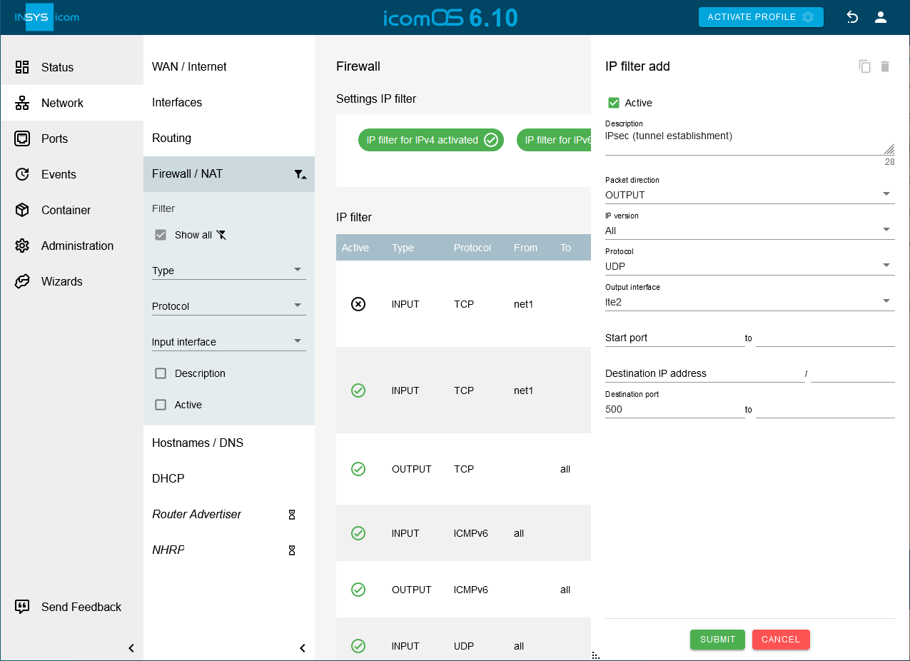
on the Network → Firewall / NAT page under IP filter to add an IP filter rule and configure this accordingly: [9]-
Description: IPsec (tunnel establishment)
-
Packet direction: OUTPUT
-
IP version: All
-
Protocol: UDP
-
Output interface: Check the WAN interface used, i.e. lte2 * or *net3.
-
Destination port: 500
-
-
Click on SUBMIT .
-
Click on
on the Network → Firewall / NAT page under IP filter to add an IP filter rule and configure this accordingly: [10]-
Description: IPsec protocol ESP
-
Packet direction: OUTPUT
-
IP version: All
-
Protocol: ESP
-
Output interface: Check the WAN interface used, i.e. lte2 * or *net3.
-
-
Click on SUBMIT .
-
Click on
on the Network → Firewall / NAT page under IP filter to add an IP filter rule and configure this accordingly: [11]-
Description: IPsec UDP Port 4500 (NAT traversal)
-
Packet direction: OUTPUT
-
IP version: All
-
Protocol: UDP
-
Output interface: Check the WAN interface used, i.e. lte2 * or *net3.
-
Destination port: 4500
-
-
Click on SUBMIT .
-
Click on
on the Network → Firewall / NAT page under IP filter to add an IP filter rule and configure this accordingly: [9]-
Description: IPsec (tunnel establishment)
-
Packet direction: INPUT
-
IP version: All
-
Protocol: UDP
-
Input interface: Check the WAN interface used, i.e. lte2 * or *net3.
-
Destination port: 500
-
-
Click on SUBMIT .
-
Click on
on the Network → Firewall / NAT page under IP filter to add an IP filter rule and configure this accordingly: footnote: ipsec[]-
Description: IPsec protocol ESP
-
Packet direction: INPUT
-
IP version: All
-
Protocol: ESP
-
Input interface: Check the WAN interface used, i.e. lte2 * or *net3.
-
-
Click on SUBMIT .
-
Click on
on the Network → Firewall / NAT page under IP filter to add an IP filter rule and configure this accordingly: footnote: ipsecnat[]-
Description: IPsec UDP Port 4500 (NAT traversal)
-
Packet direction: INPUT
-
IP version: All
-
Protocol: UDP
-
Input interface: Check the WAN interface used, i.e. lte2 * or *net3.
-
Destination port: 4500
-
-
Click on SUBMIT .
-
Click on
on the Network → Firewall / NAT page under IP filter to add an IP filter rule and configure this accordingly: [12]-
Description: Traffic through the IPsec tunnel sent by the router
-
Packet direction: OUTPUT
-
IP version: All
-
Protocol: All
-
Output interface:
 ipsec1
-
-
Click on SUBMIT .
-
Click on
on the Network → Firewall / NAT page under IP filter to add an IP filter rule and configure this accordingly: [13]-
Description: Traffic through the IPsec tunnel sent to the router
-
Packet direction: INPUT
-
IP version: All
-
Protocol: All
-
Input interface:
ipsec1
-
-
Click on SUBMIT .
-
Click on
on the Network → Firewall / NAT page under IP filter to add an IP filter rule and configure this accordingly: [14]-
Description: GRE (tunnel establishment)
-
Packet direction: OUTPUT
-
IP version: All
-
Protocol: GRE
-
Output interface: Check the WAN interface used, i.e. lte2 * or *net3.
-
-
Click on SUBMIT .
-
Click on
on the Network → Firewall / NAT page under IP filter to add an IP filter rule and configure this accordingly: [14]-
Description: GRE (tunnel establishment)
-
Packet direction: INPUT
-
IP version: All
-
Protocol: GRE
-
Input interface: Check the WAN interface used, i.e. lte2 * or *net3.
-
-
Click on SUBMIT .
-
Click on
on the Network → Firewall / NAT page under IP filter to add an IP filter rule and configure this accordingly: [15]-
Description: Traffic from the local net through the GRE tunnel
-
Packet direction: FORWARD
-
IP version: All
-
Protocol: All
-
Input interface:
net1, net2 -
Output interface::
gre1
-
-
Click on SUBMIT .
-
Click on
on the Network → Firewall / NAT page under IP filter to add an IP filter rule and configure this accordingly: [16]-
Description: Traffic through the GRE tunnel to the local net
-
Packet direction: FORWARD
-
IP version: All
-
Protocol: All
-
Input interface:
gre1 -
Output interface:
net1, net2
-
-
Click on SUBMIT .
-
Activate the profile with a click on ACTIVATE PROFILE
 .
. -
Observe the establishment of the WAN chain containing the tunnels on the
 Status → Dashboard page in the WAN chain section.
 -
Click on the
 Administration → Debugging page on OPEN DEBUG TOOLS
  , select the Tool Ping, enter available IP addresses of the remote subnets under Parameter and click on SEND to verify the connectivity.
We’ve prepared the following ASCII configuration file for adding the filter rules in one go instead of entering them one by one as described in detail above. Copy and paste it to your text editor or download it using the link below. Don’t forget to adjust it to your application if required.
The ASCII configuration file will add all filters as above with both possible WAN interfaces that can be created by the Startup wizard, i.e. lte2 and net3.
Refer to Adding a List Parameter to a Profile Using Lua to see how to apply an ASCII configuration file to a profile.
netfilter.ip_filter.rule.add
netfilter.ip_filter.rule[last].rule_active=1
netfilter.ip_filter.rule[last].rule_description=IPsec (tunnel establishment)
netfilter.ip_filter.rule[last].rule_direction=output
netfilter.ip_filter.rule[last].rule_protocol=udp
netfilter.ip_filter.rule[last].rule_output_if=lte2,net3
netfilter.ip_filter.rule[last].rule_dport=500
netfilter.ip_filter.rule[last].rule_ipversion=all

netfilter.ip_filter.rule.add
netfilter.ip_filter.rule[last].rule_active=1
netfilter.ip_filter.rule[last].rule_description=IPsec protocol ESP
netfilter.ip_filter.rule[last].rule_direction=output
netfilter.ip_filter.rule[last].rule_protocol=esp
netfilter.ip_filter.rule[last].rule_output_if=lte2,net3
netfilter.ip_filter.rule[last].rule_ipversion=all

netfilter.ip_filter.rule.add
netfilter.ip_filter.rule[last].rule_active=1
netfilter.ip_filter.rule[last].rule_description=IPsec UDP Port 4500 (NAT traversal)
netfilter.ip_filter.rule[last].rule_direction=output
netfilter.ip_filter.rule[last].rule_protocol=udp
netfilter.ip_filter.rule[last].rule_output_if=lte2,net3
netfilter.ip_filter.rule[last].rule_dport=4500
netfilter.ip_filter.rule[last].rule_ipversion=all

netfilter.ip_filter.rule.add
netfilter.ip_filter.rule[last].rule_active=1
netfilter.ip_filter.rule[last].rule_description=IPsec (tunnel establishment)
netfilter.ip_filter.rule[last].rule_direction=input
netfilter.ip_filter.rule[last].rule_protocol=udp
netfilter.ip_filter.rule[last].rule_input_if=lte2,net3
netfilter.ip_filter.rule[last].rule_dport=500
netfilter.ip_filter.rule[last].rule_ipversion=all

netfilter.ip_filter.rule.add
netfilter.ip_filter.rule[last].rule_active=1
netfilter.ip_filter.rule[last].rule_description=IPsec protocol ESP
netfilter.ip_filter.rule[last].rule_direction=input
netfilter.ip_filter.rule[last].rule_protocol=esp
netfilter.ip_filter.rule[last].rule_input_if=lte2,net3
netfilter.ip_filter.rule[last].rule_ipversion=all

netfilter.ip_filter.rule.add
netfilter.ip_filter.rule[last].rule_active=1
netfilter.ip_filter.rule[last].rule_description=IPsec UDP Port 4500 (NAT traversal)
netfilter.ip_filter.rule[last].rule_direction=input
netfilter.ip_filter.rule[last].rule_protocol=udp
netfilter.ip_filter.rule[last].rule_input_if=lte2,net3
netfilter.ip_filter.rule[last].rule_dport=4500
netfilter.ip_filter.rule[last].rule_ipversion=all

netfilter.ip_filter.rule.add
netfilter.ip_filter.rule[last].rule_active=1
netfilter.ip_filter.rule[last].rule_description=Traffic through the IPsec tunnel sent by the router
netfilter.ip_filter.rule[last].rule_direction=output
netfilter.ip_filter.rule[last].rule_protocol=all
netfilter.ip_filter.rule[last].rule_output_if=ipsec1
netfilter.ip_filter.rule[last].rule_ipversion=all

netfilter.ip_filter.rule.add
netfilter.ip_filter.rule[last].rule_active=1
netfilter.ip_filter.rule[last].rule_description=Traffic through the IPsec tunnel sent to the router
netfilter.ip_filter.rule[last].rule_direction=input
netfilter.ip_filter.rule[last].rule_protocol=all
netfilter.ip_filter.rule[last].rule_input_if=ipsec1
netfilter.ip_filter.rule[last].rule_ipversion=all

netfilter.ip_filter.rule.add
netfilter.ip_filter.rule[last].rule_active=1
netfilter.ip_filter.rule[last].rule_description=GRE (tunnel establishment)
netfilter.ip_filter.rule[last].rule_direction=output
netfilter.ip_filter.rule[last].rule_protocol=gre
netfilter.ip_filter.rule[last].rule_output_if=lte2,net3
netfilter.ip_filter.rule[last].rule_ipversion=all

netfilter.ip_filter.rule.add
netfilter.ip_filter.rule[last].rule_active=1
netfilter.ip_filter.rule[last].rule_description=GRE (tunnel establishment)
netfilter.ip_filter.rule[last].rule_direction=input
netfilter.ip_filter.rule[last].rule_protocol=gre
netfilter.ip_filter.rule[last].rule_input_if=lte2,net3
netfilter.ip_filter.rule[last].rule_ipversion=all

netfilter.ip_filter.rule.add
netfilter.ip_filter.rule[last].rule_active=1
netfilter.ip_filter.rule[last].rule_description=Traffic from the local net through the GRE tunnel
netfilter.ip_filter.rule[last].rule_direction=forward
netfilter.ip_filter.rule[last].rule_protocol=all
netfilter.ip_filter.rule[last].rule_input_if=net1,net2
netfilter.ip_filter.rule[last].rule_output_if=gre1
netfilter.ip_filter.rule[last].rule_ipversion=all

netfilter.ip_filter.rule.add
netfilter.ip_filter.rule[last].rule_active=1
netfilter.ip_filter.rule[last].rule_description=Traffic through the GRE tunnel to the local net
netfilter.ip_filter.rule[last].rule_direction=forward
netfilter.ip_filter.rule[last].rule_protocol=all
netfilter.ip_filter.rule[last].rule_input_if=gre1
netfilter.ip_filter.rule[last].rule_output_if=net1,net2
netfilter.ip_filter.rule[last].rule_ipversion=all
Troubleshooting
-
Disable the IP filters for IPv4 in the
Network → Firewall / NAT menu under Settings IP filter to check whether incorrect filter settings are the reason for connection problems.
Back to the Configuration Guides for icom OS Smart Devices
Back to overview