Various routers of INSYS icom provide the option to set up a redundant WAN connection to increase the availability.
This Configuration Guide shows how to configure a redundant WAN connection.
Situation
An INSYS router has a primary WAN connection over Ethernet, for example to an Internet router. It is necessary to configure a secondary WAN connection that can be used in case the primary WAN connection fails. This can be realised using the connection check function.
Solution
It is prerequisite that you have access to the web interface of the router and the router has been commissioned for Internet access via WAN over Ethernet using the Startup Wizard. The Startup Wizard configures a WAN interface and a local LAN network for your router. You’ll now add an additional Internet connection (secondary WAN connection) and configure the connection check of the primary WAN connection. A WAN chain defines a WAN connection. It is the sequential arrangement of interfaces that defines the establishment of a WAN connection.
|
|
Depending on the router, a wide variety of combinations of primary and secondary WAN connections are possible, including to alternative mobile providers in the event of a provider failure. The configuration is similar to the example configuration with Ethernet and cellular radio discussed in this Configuration Guide. |
-
Open the user interface of the router in a browser: insys.icom [1]
-
Click on
 behind the LTE interface lte2 on the
  Network → Interfaces page to edit this LTE interface.
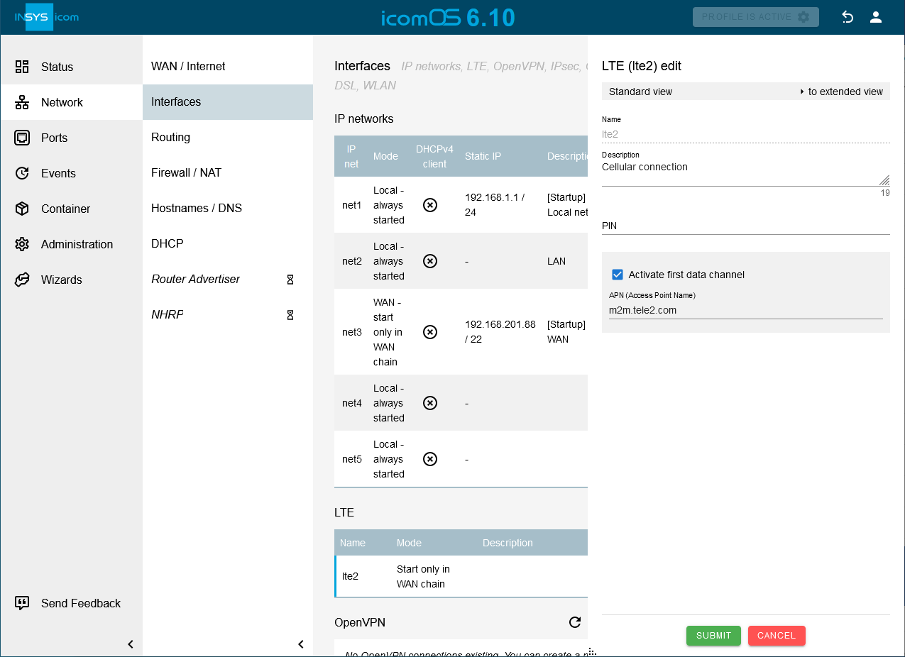
-
Enter a Description and the APN of your provider.
-
Click on SUBMIT .
-
Click on
 on the Network → WAN / Internet page to add a new WAN chain and enter a Description.
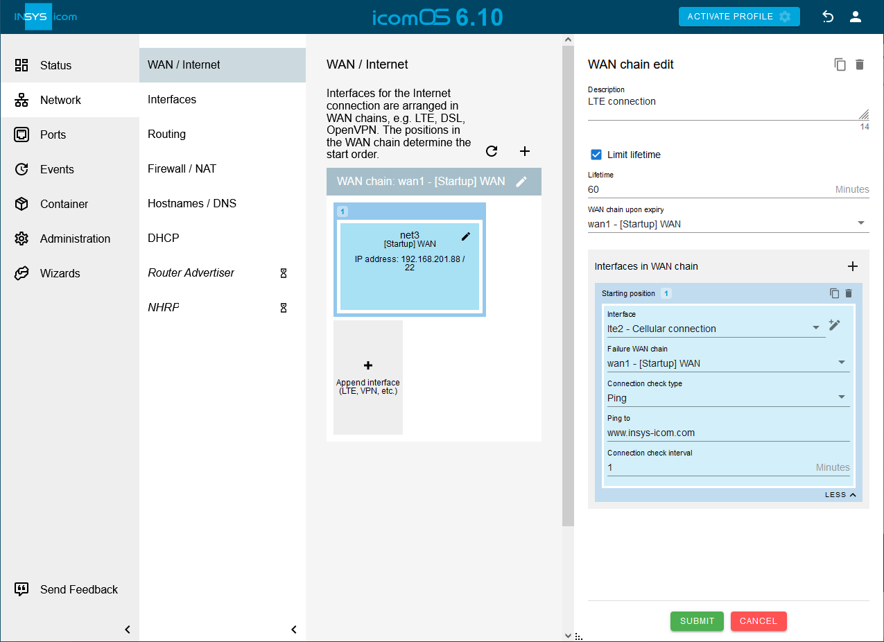
-
Check the option Limit lifetime, enter a lifetime for this WAN chain and select under WAN chain upon expiry wan1 as WAN chain. [2].
-
Click in the Interfaces in WAN chain section on
and add above added LTE interface. -
Click on MORE
 at the bottom of Interfaces in WAN chain and select the WAN chain wan1 under Failure WAN chain.
 -
Select under Connection check type Ping, enter under Ping to e. g. www.insys-icom.com and enter a Connection check interval.
-
Click on SUBMIT .
-
Click on
behind the WAN chain wan1 on the Network → WAN / Internet page to edit this.
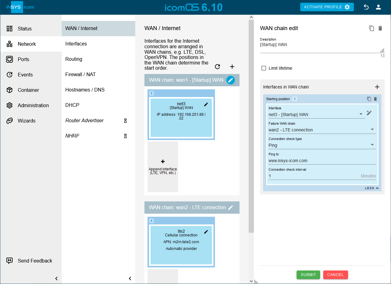
-
Click on MORE
at the bottom of Interfaces in WAN chain and select the WAN chain wan2 under Failure WAN chain. -
Select under Connection check type Ping, enter under Ping to e. g. www.insys-icom.com and enter a Connection check interval.
-
Click on SUBMIT .
-
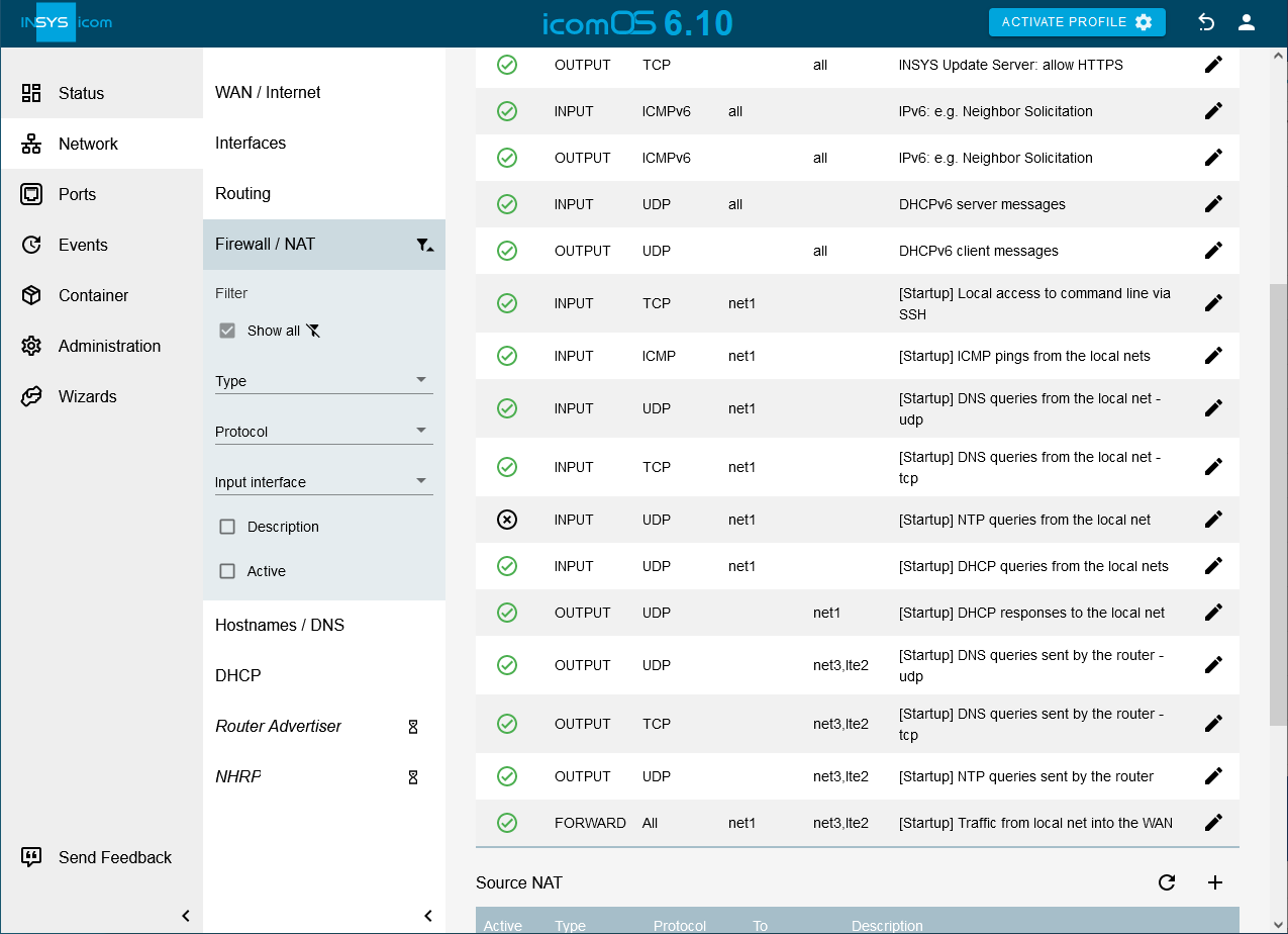
Click on the
Network → Firewall / NAT page in the IP filter section on behind the OUTPUT rule [Startup] DNS queries sent by the router - udp and add above added LTE interface under Output interface.
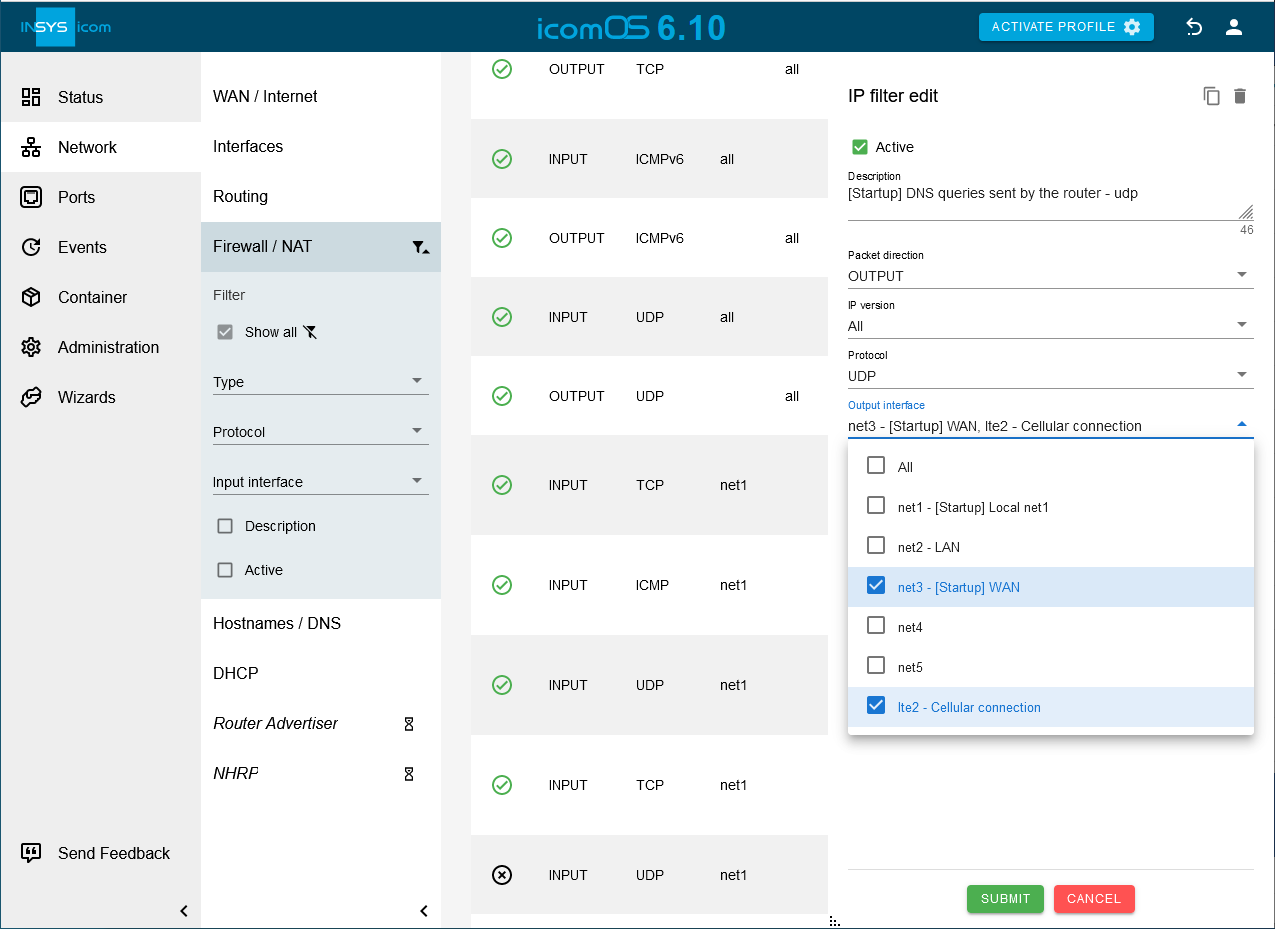
-
Click on SUBMIT .
-
Add the LTE interface to the output interfaces in the same way for the filter rules [Startup] DNS queries sent by the router - tcp, [Startup] NTP queries sent by the router _ and _[Startup] Traffic from local net into the WAN, for which the interface net3 is also specified as the output interface.
-
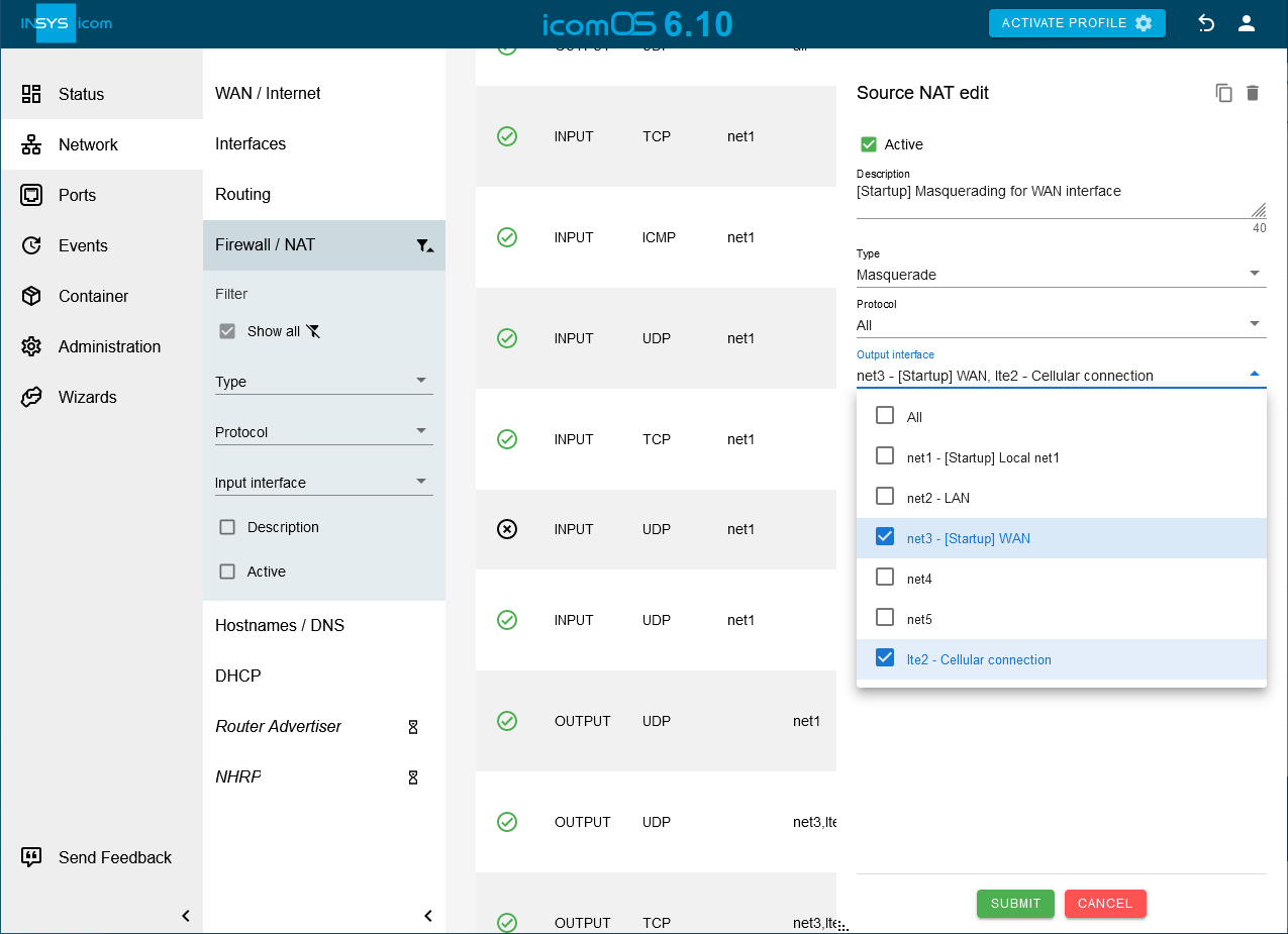
Click on the
Network → Firewall / NAT page in the the Source NAT section on behind the Masquerade rule [Startup] Masquerading for WAN interface and add above added LTE interface under Output interface.
-
Click on SUBMIT .
-
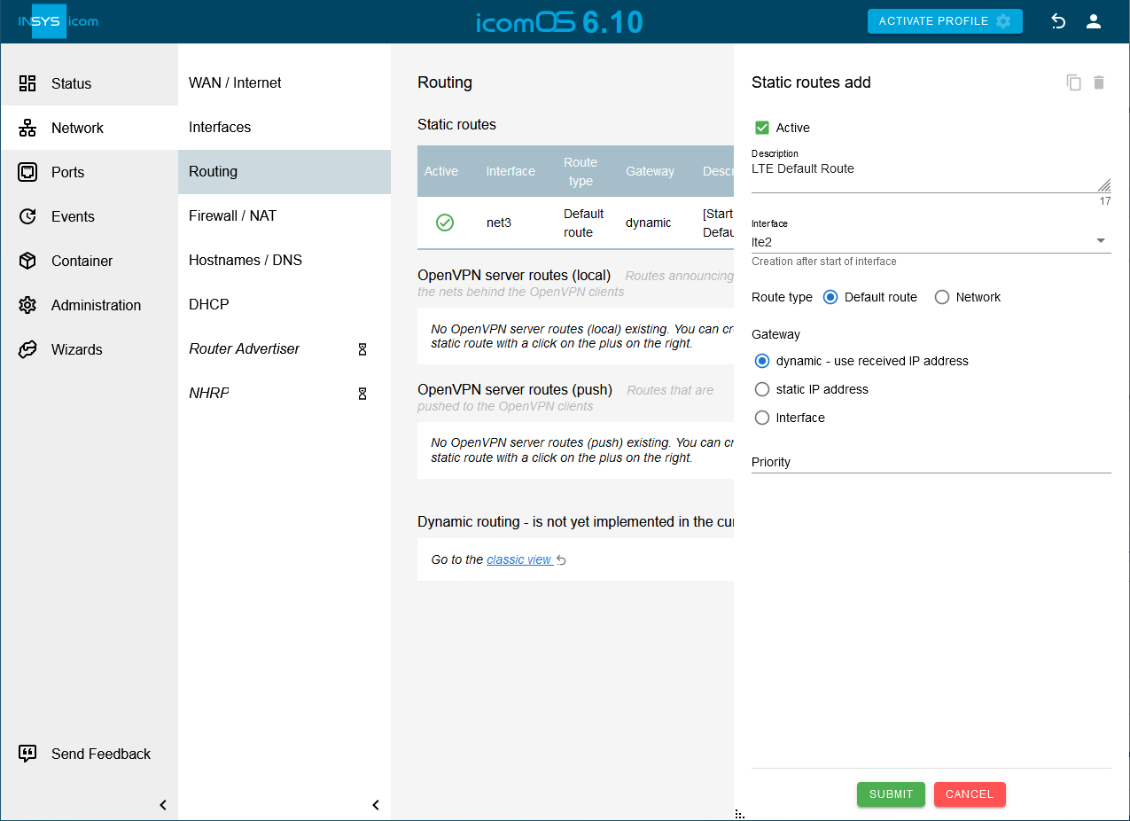
Click on
on the Network → Routing page in the Static routes section to add a new static route and enter a Description:
-
Select the LTE interface lte2 specified above under Interface and Default route as Route type.
-
Select dynamic - use received IP address under Gateway.
-
Click on SUBMIT .
-
Activate the profile with a click on ACTIVATE PROFILE
 .
.
Result testing
-
Open the
 Status → Dashboard page and observe the establishment of the WAN chain in the WAN chain section.
 -
Disconnect the Ethernet cable used for the Internet connection in port 5 and wait for the connection check interval to verify that the WAN connection changes to the redundant WAN connection.
-
Reconnect the Ethernet cable to verify that the WAN connection changes back to the normal WAN connection after the lifetime of the redundant WAN connection has expired.
Troubleshooting
-
You can temporarily disable the IP filters for IPv4 on the
Network → Firewall / NAT page in the Settings IP filter section to find out if incorrect filter settings are the cause of problems. -
Observe on the
Status → Log view page which process might fail.
Back to the Configuration Guides for icom OS routers
Back to overview