INSYS routers with icom OS provide an integrated Linux environment that is able to virtualise own, independent systems using Linux containers (LXC).
This also makes it possible to run the graphical development tool Node-RED on the router for example in order to realise your own IoT applications.
1. Situation
You have a humidity/temperature sensor with Modbus RTU (RS485). You want to read out humidity and temperature using Node-RED and visualise the read values in a dashboard. We will use an open source IoT platform for this with Thingsboard.
2. Solution
Connect the sensor to the RS485 interface of your INSYS icom router (e. g. From the ECR family or MRX family with MRcard SI). Use the Node-Red container provided by us and install it to your router. Use it to create your application that reads the values from the sensor and make these values available to a Thingsboard dashboard then.
2.1. Connecting the sensor to the router
We have used a commercial humidity/temperature sensor with RS485 interface for this example. Connect the sensor to the power supply and RS485 interface of the router. Pay attention to the correct polarity of the connector for the RS485 data lines (refer to the Installation manual of the router as well as the technical documentation of your sensor).
|
|
The RS485 data line son our routers are identified with D+ and D-. The designations TX+/RX+ (for D+) and TX-/RX- (for D-) are also common. If the designations A and B are used, these are not always clear, if no /- is appended. Often, A is used for D and B for D-, but this is not always consistent. If in doubt, the two wires would then have to be inverted once. |
2.2. Configuring the Internet connection of the router
The router must have an internet connection in order to transmit the read data to Thingsboard. A startup wizard permits an easy configuration of the Internet connection.
-
Open the user interface of the router in a browser: insys.icom [1]
-
Click in the
 Wizards → Startup wizard menu on START
  .
. -
If necessary, change the time and synchronisation settings and click on NEXT
 .
. -
Enter the desired authentication credentials and click on NEXT
. -
Configure the respective Internet connection and click on NEXT
. -
Configure your VPN connection (not necessary for this example) and click on NEXT
. -
If necessary, change the LAN connection settings (not necessary for this example) and click on NEXT
. -
If necessary, upload a configuration for the icom Router Management to the router (not necessary for this example).
-
Click on RUN WIZARD .
-
Observe the execution of the wizard and click on EXIT WIZARD .
The startup wizard has configured the router for the Internet connection.
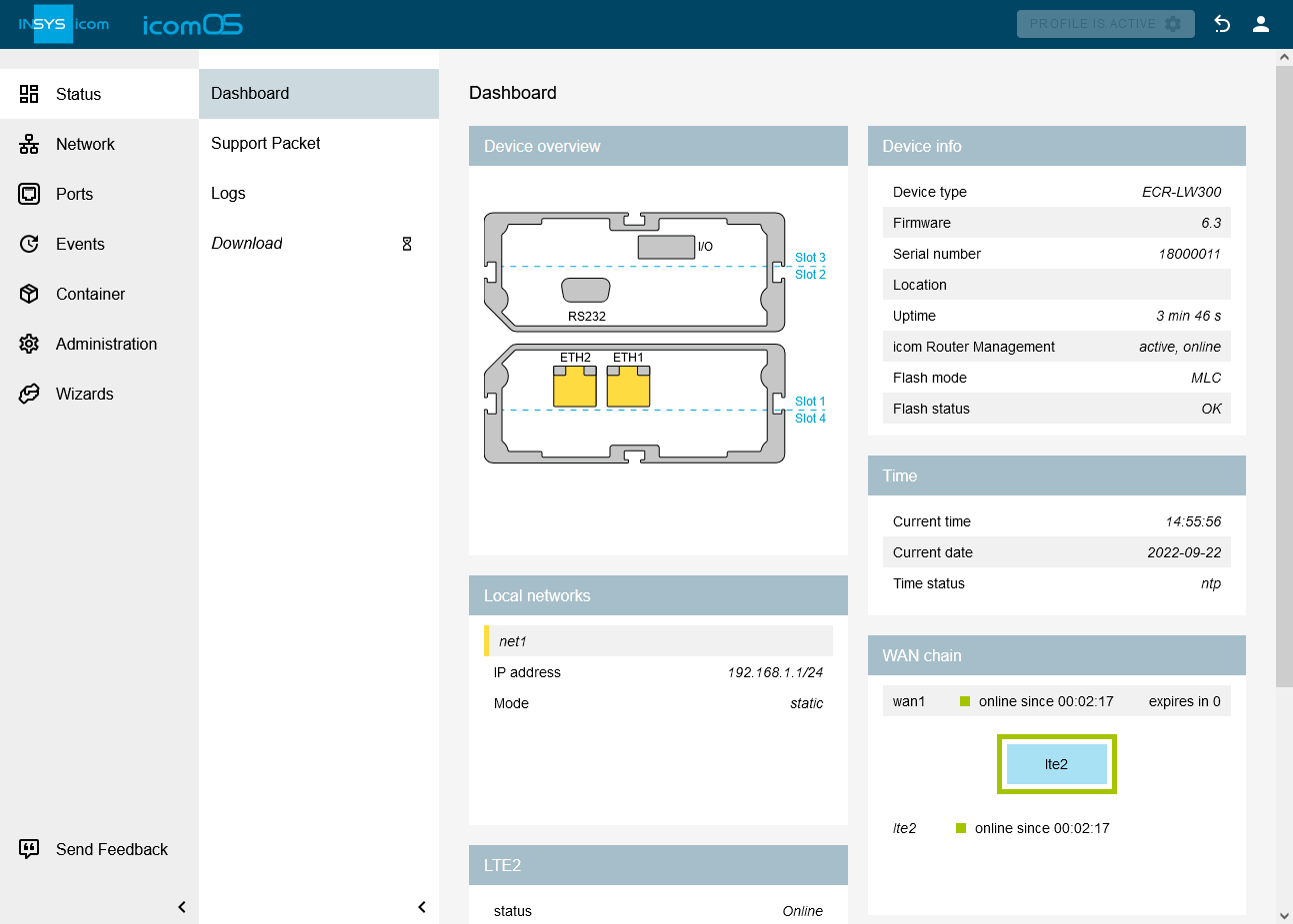
You can follow the establishment of the WAN chain for the Internet connection in the ![]() Status → Dashboard menu in the WAN chain section.
Status → Dashboard menu in the WAN chain section.
2.3. Installing the Node-RED container to the router
Node-RED is a graphical development tool that is executed in a container on the router.
|
|
In case an icom Data Suite is installed on your router, disable their container in the |
-
Open the INSYS Container page and download the Node-RED container.
-
Open the user interface of the router in a browser: insys.icom [1]
-
Click in the
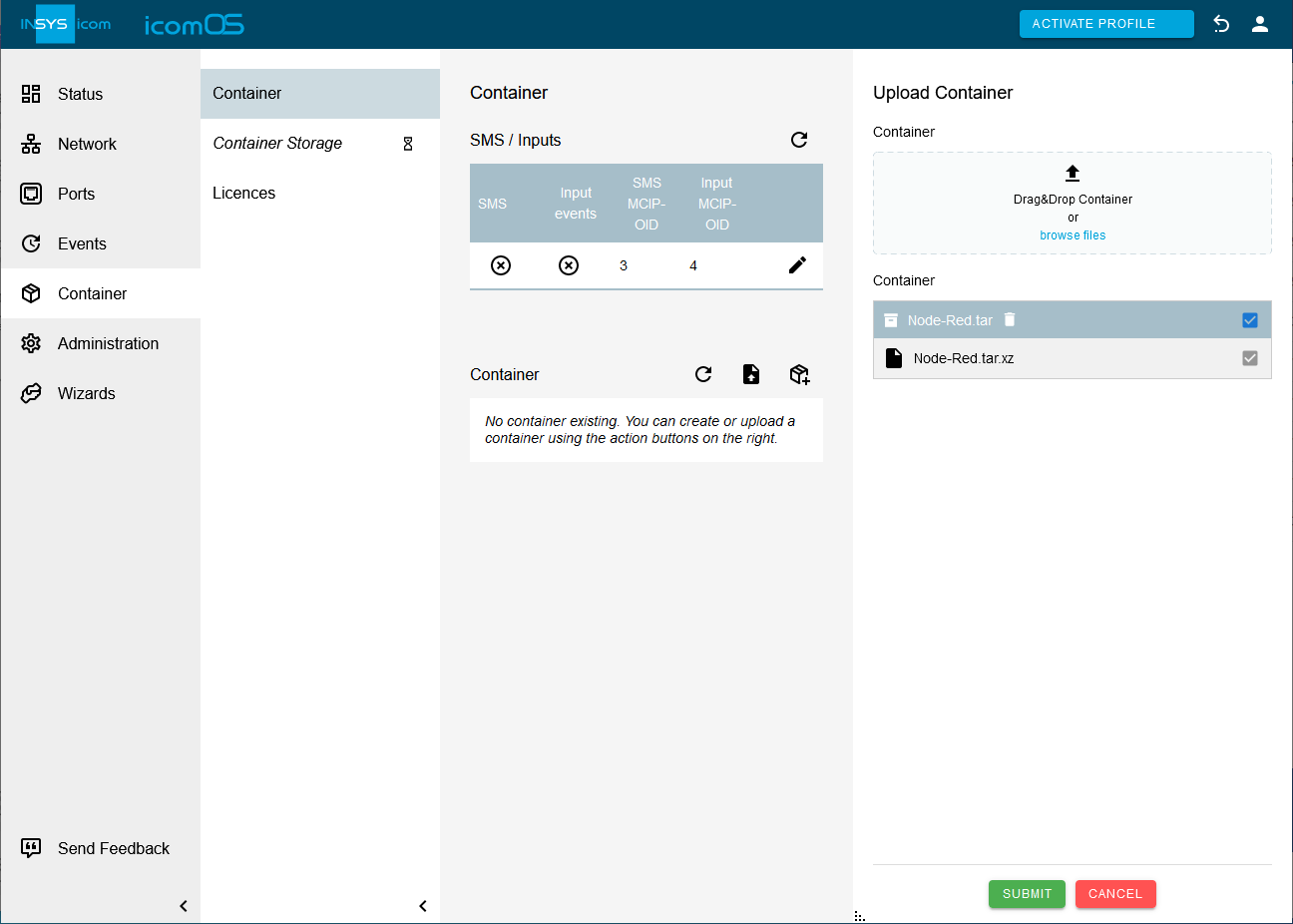
 Container → Container menu on
  and upload the container to the router.
-
Click on SUBMIT .
-
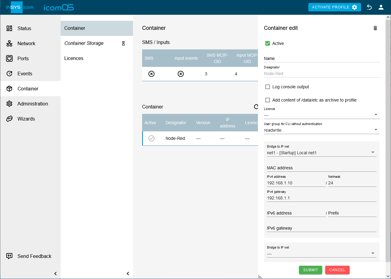
Click on
 for the previously uploaded container and edit the container configuration:
-
User group for CLI without authentication: Read/Write
-
Bridge to IP net: net1
-
IPv4 address: 192.168.1.10 / 24
-
Ipv4 gateway: 192.168.1.1
-
-
Click on SUBMIT .
-
Click on ACTIVATE PROFILE
 .
.
2.4. Establishing the SSH connection to the container and preparing it
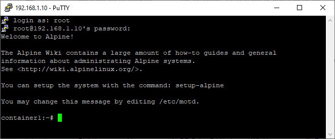
The Node-RED container features Alpine Linux, which can be accessed via an SSH connection.
-
Connect to the container using a terminal program (such as PuTTY) via an SSH connection.
-
Address: 192.18.1.10 (or as specified above)
-
User name: root
-
Password: root
-
-
Install the Python compiler and other tools to install the Modbus package in Node-RED in one of the next steps. To do this, enter the following commands in the command line (or shell):
container1:~# apk add python3
container1:~# apk add make
container1:~# apk add g++
container1:~# apk add gcc
container1:~# apk add linux-headers
You have now prepared the container for the installation of the Modbus module in Node-RED.
2.5. Installing the Modbus packet in Node-RED
-
Open the user interface of Node-RED under the address http://192.168.1.10:1880 (https is not supported!).
-
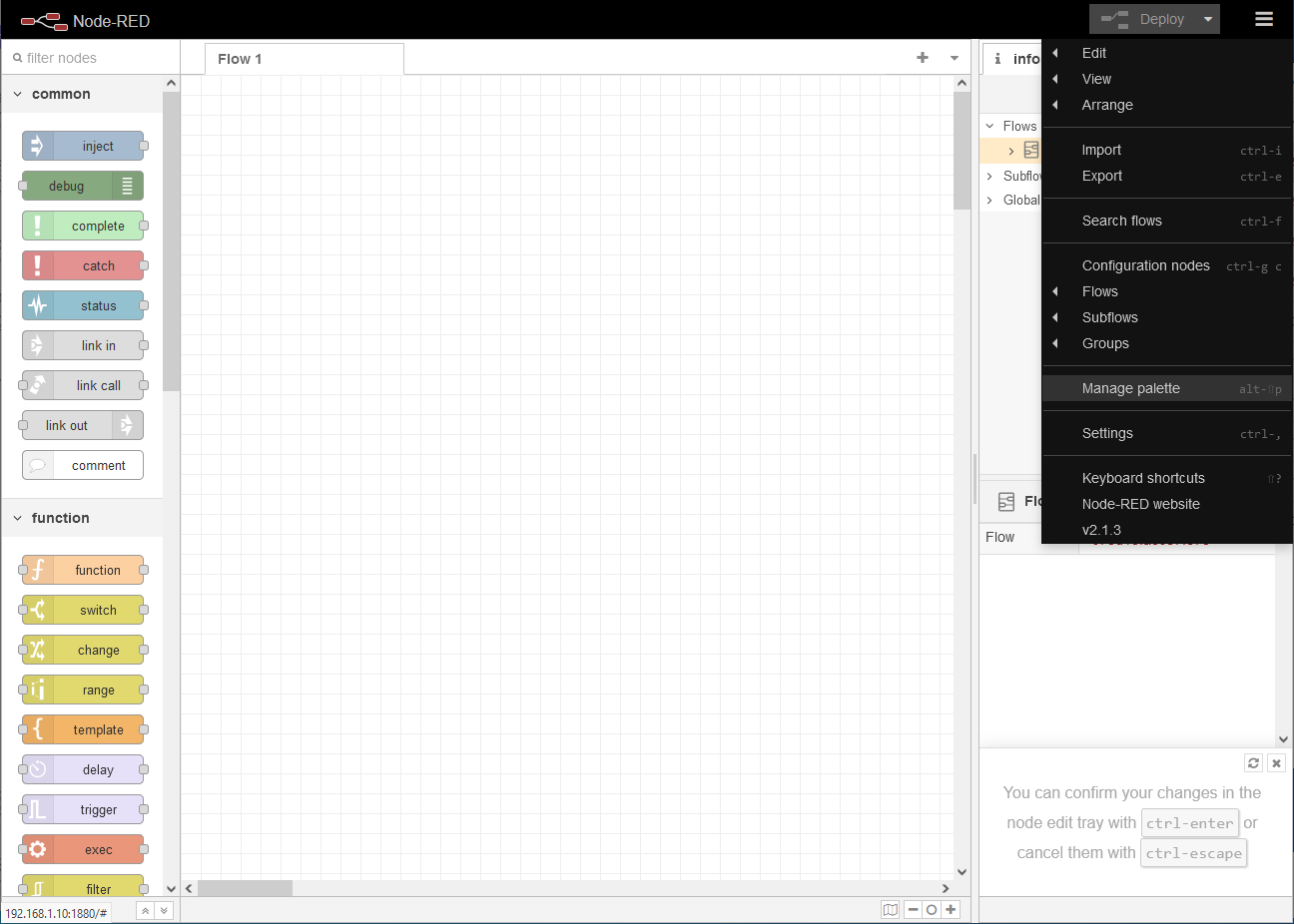
Click on
 and select Manage palette.
 -
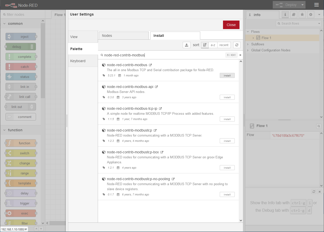
Search on the Install tab for the node-red-contrib-modbus module and install it with a click on Install.
-
Select to the Nodes tab and click on Close .
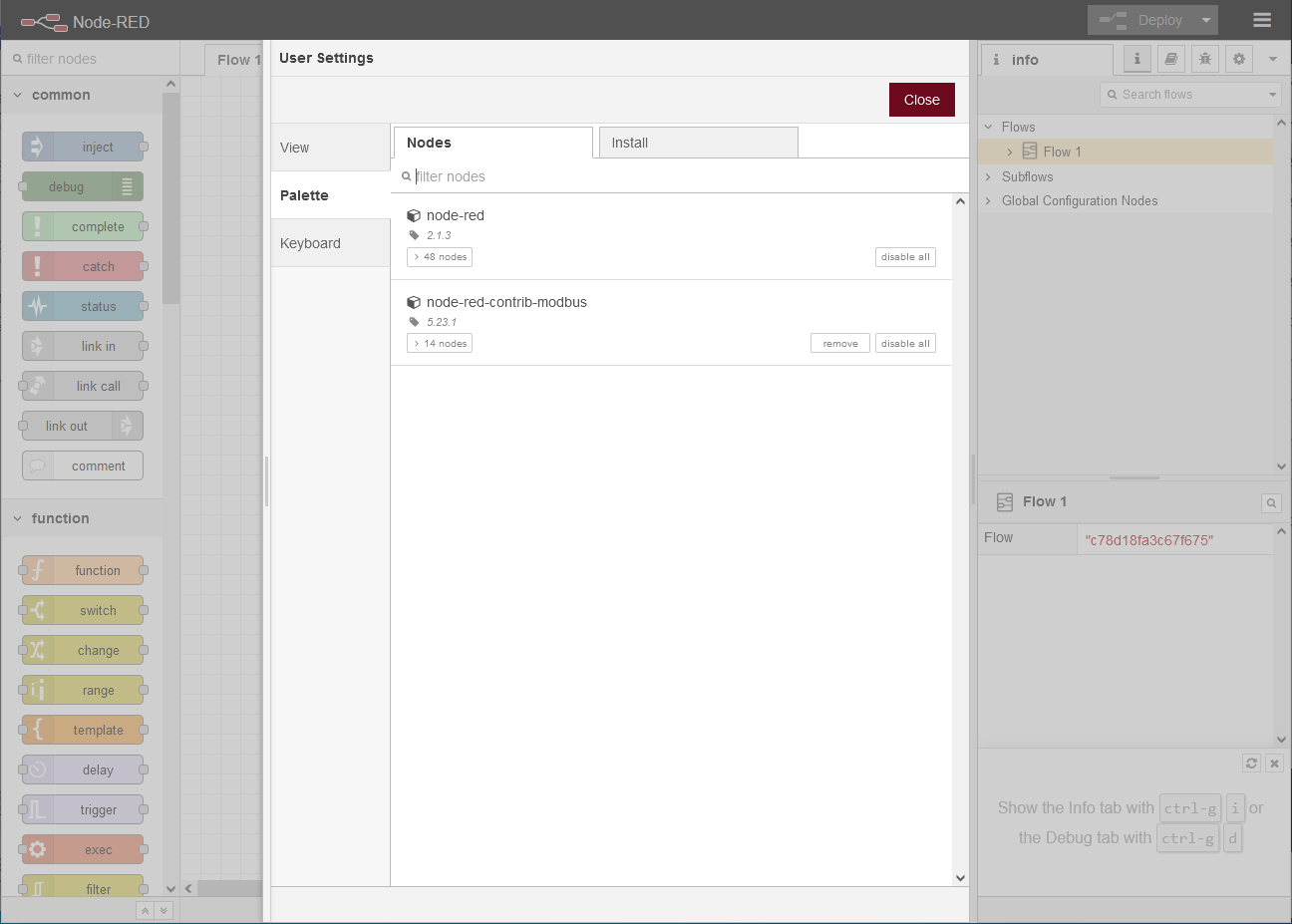
You have now installed the Modbus module in Node-RED and can continue with the development of your application.
|
|
After installing the Modbus module, you can remove the packages you just installed to reduce the size of the container.
To do this, use the following commands via the SSH connection (refer to Establishing the SSH connection to the container and preparing it):container1:~# apk del python3container1:~# apk del makecontainer1:~# apk del g++container1:~# apk del gcccontainer1:~# apk del linux-headers
|
2.6. Creating a flow in Node-RED
A flow will now be created that reads data from the Modbus sensor and transmits this data to Thingsboard. Flow in Node-RED refers to the application defined by interconnected input, output and processing nodes.
2.6.1. Creating a Modbus-Read node for the temperature sensor
-
Select a Modbus-Read node at the very bottom left and drag it onto the workspace.
-
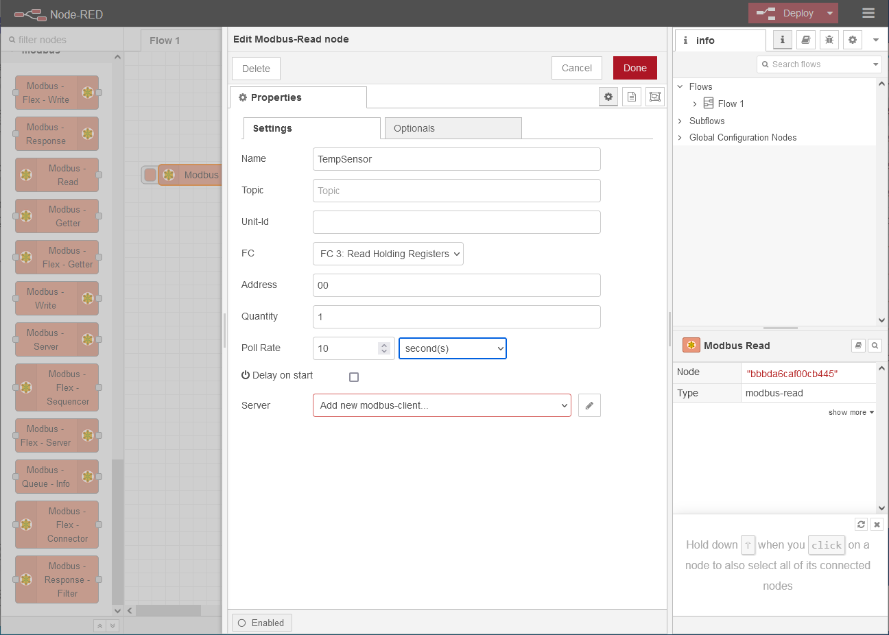
Double-click the node to edit its properties on the Settings tab (the following settings apply to the sensor we use; refer to the documentation of your sensor for the appropriate values):
-
Name: TempSensor
-
FC: FC3: Read Holding Registers
-
Address: 00
-
Quantity: 1
-
Poll Rate: 10 second(s)
-
-
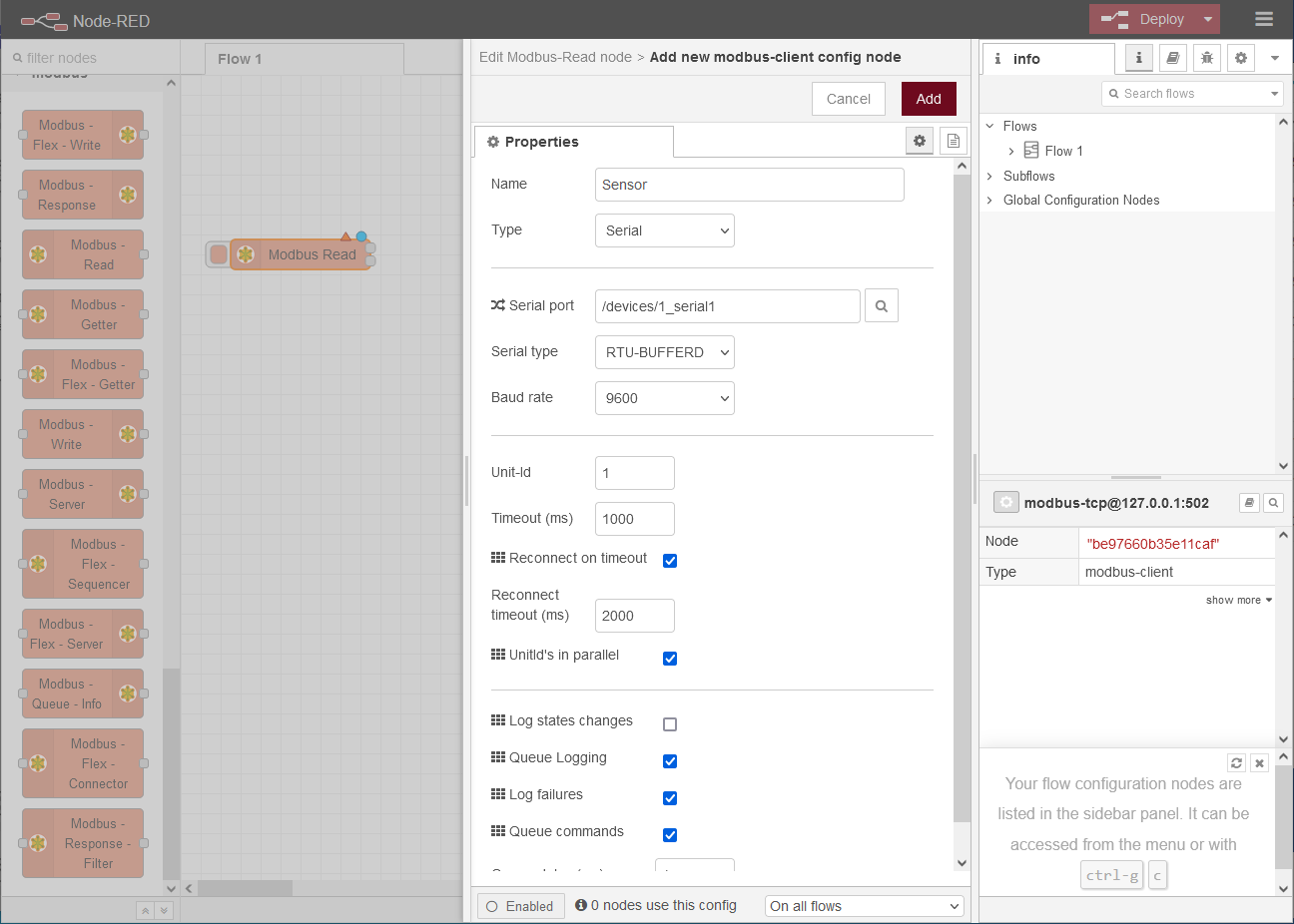
Click behind Server on
 to add a new Modbus server and configure it:
 -
Click on Update .
-
Change to the Optionals tab and check the options Show Activities and Show Errors.
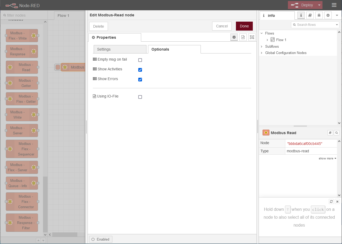
-
Click on Done .
2.6.2. Creating a function node for temperature conversion
-
Select a function function node and drag it onto the workspace.
-
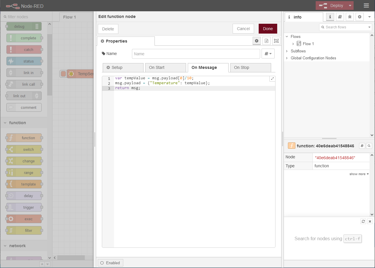
Double-click the node to edit its properties on the On Message tab.
-
Copy the following code into the message window:
var tempValue = msg.payload[0]/10;
msg.payload = {"Temperature": tempValue};
return msg;
-
Click on Done .
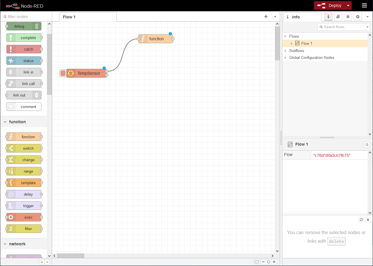
2.6.3. Connecting the nodes to a flow
-
Connect the two nodes by clicking on a connection point of one node and drawing a line to the other node.
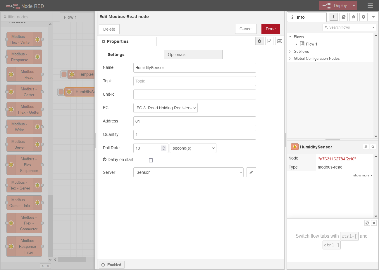
2.6.4. Creating a Modbus-Read node for the humidity sensor
-
Add another Modbus-Read node and configure it:
-
Name: HuniditySensor
-
FC: FC3: Read Holding Registers
-
Address: 01
-
Quantity: 1
-
Poll Rate: 10 second(s)
-
Server: select the already added server Sensor
-
-
Change to the Optionals tab and check the options Show Activities and Show Errors.
-
Click on Done .
2.6.5. Creating a function node for temperature conversion
-
Add another function node function and configure it:
var humidityValue = msg.payload[0]/10;
msg.payload = {"Humidity": humidityValue};
return msg;
-
Click on Done .
-
Connect the two nodes by clicking on a connection point of one node and drawing a line to the other node.
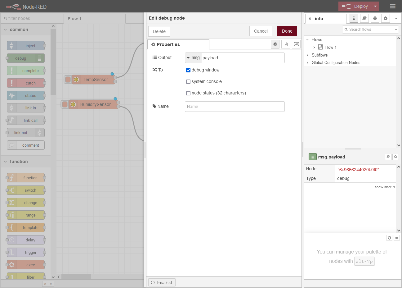
2.6.6. Creating a debug node for checkng the values
-
Select a common debug node and drag it onto the workspace.
-
Double-click the node to edit its properties.
-
Select as Output msg.payload to output the message generated by the function nodes in a debug window of Node-RED.
-
Click on Done .
-
Connect the outputs of the two function nodes to the input of the debug node.
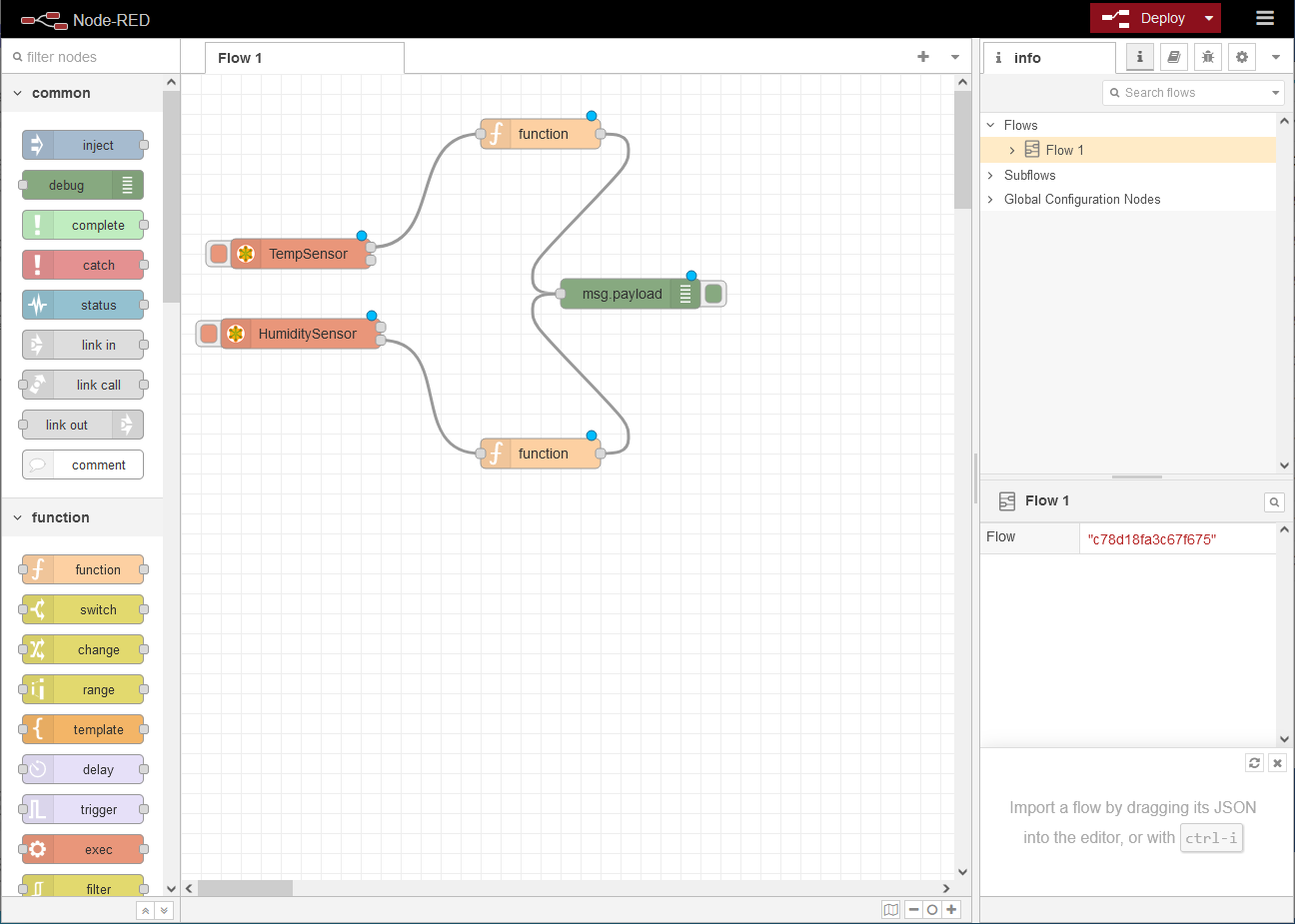
2.6.7. Deploying the flow in the application and checking the function of the application
-
Click on Deploy in the top right corner of the title bar to deploy the flow.
-
Click in the right side bar on
 to open the Debug tab.
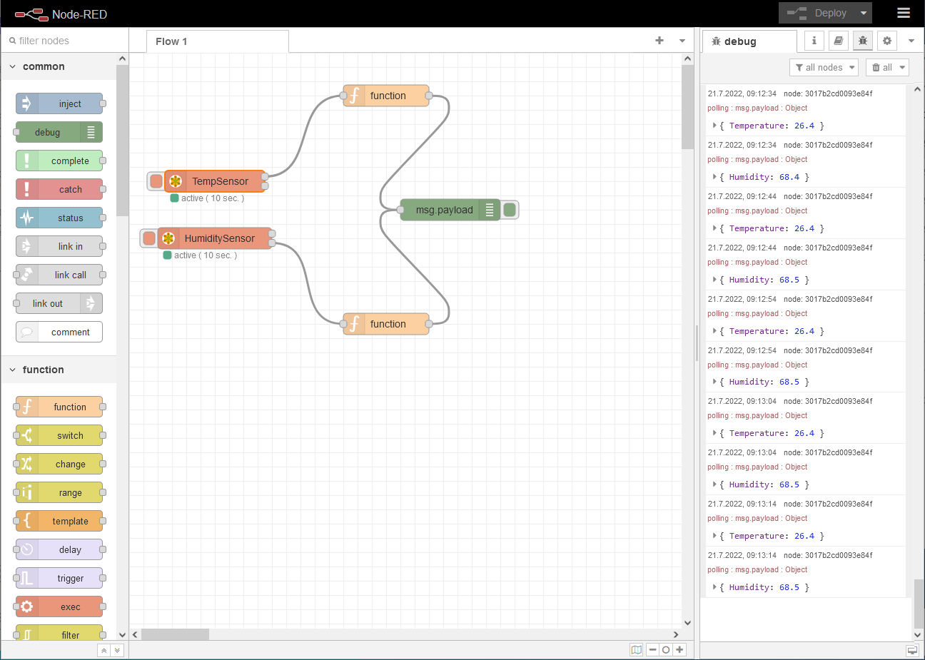
A green dot under the Modbus-Read nodes indicates the Modbus connection status. You can monitor the incoming values of the sensor for temperature and humidity in the debug window.
2.7. Creating and configuring a Thingsboard account
To be able to visualise read-out data using Thingsboard, a Thingsboard account is required. If a Thingsboard account does not yet exist, it must be created beforehand. Moreover, the device must be created in Thingsboard and an access token must be generated.
-
Open Thingsboard, set up an account if not already done and log in.
-
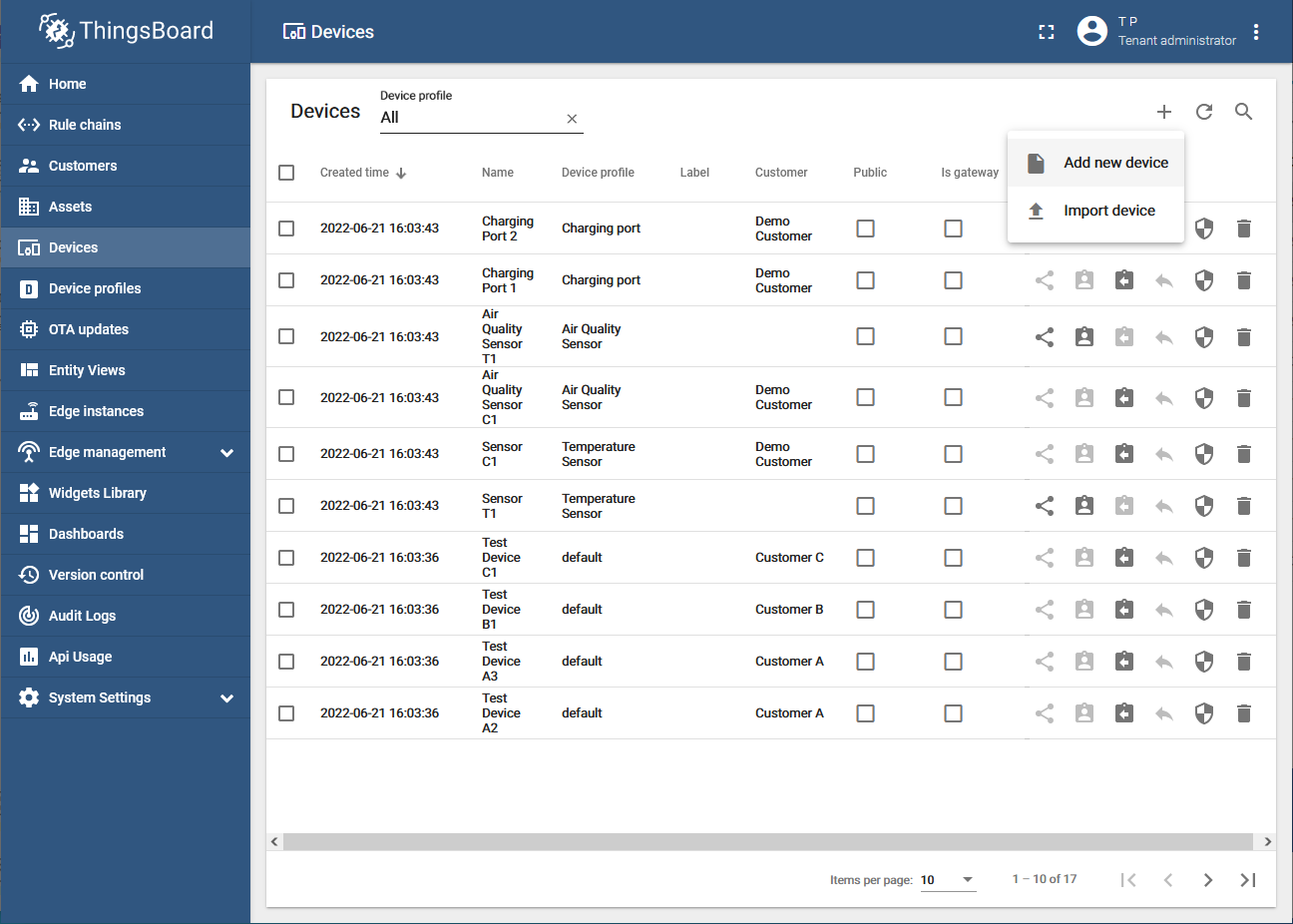
Change to the
 Devices menu and click on
  Add Device →
  Add new device.
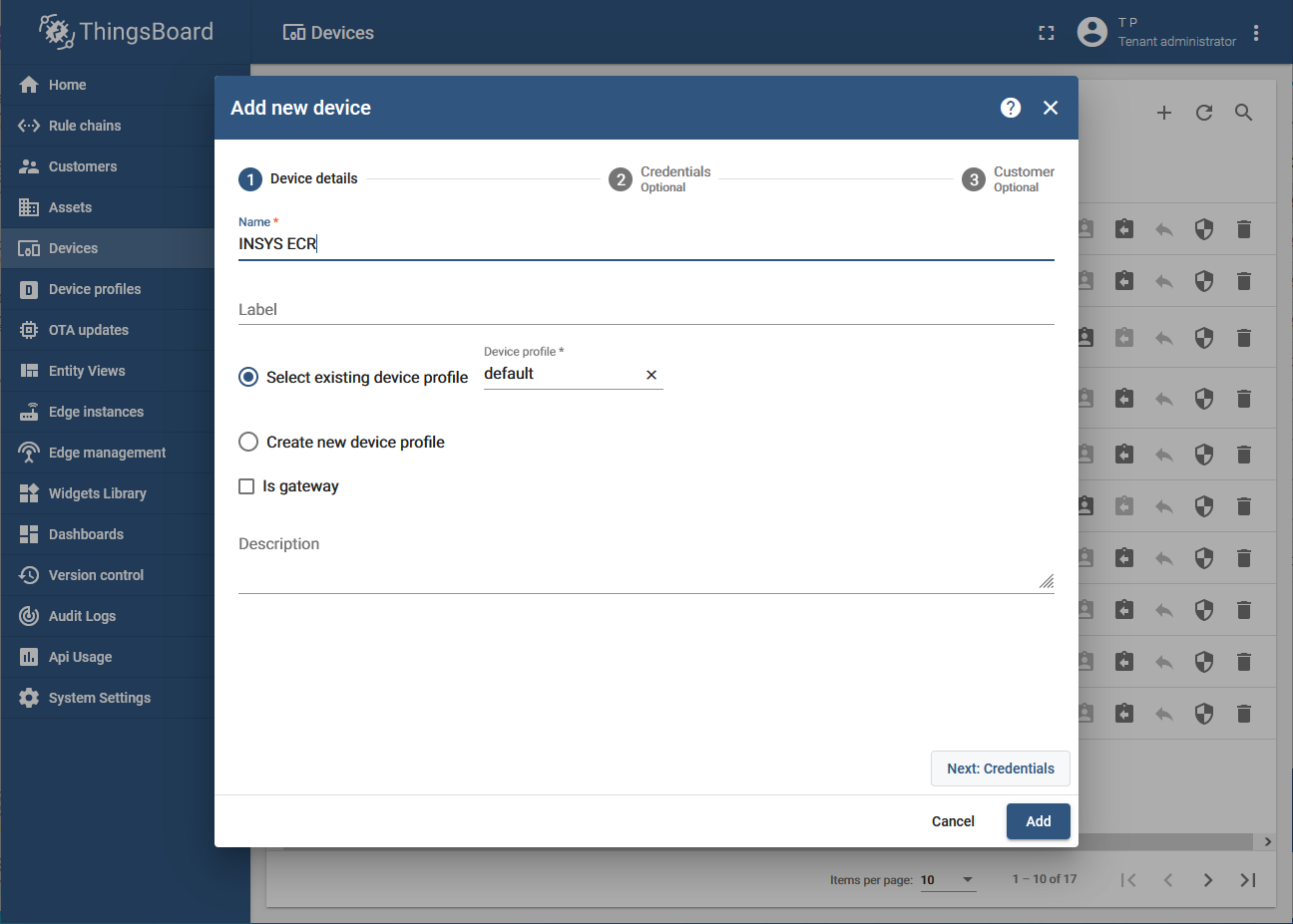
-
Enter a suitable name for the device and click on Next: Credentials.
-
Activate Add credentials, select Access token under Credentials type and enter a string under Access token.
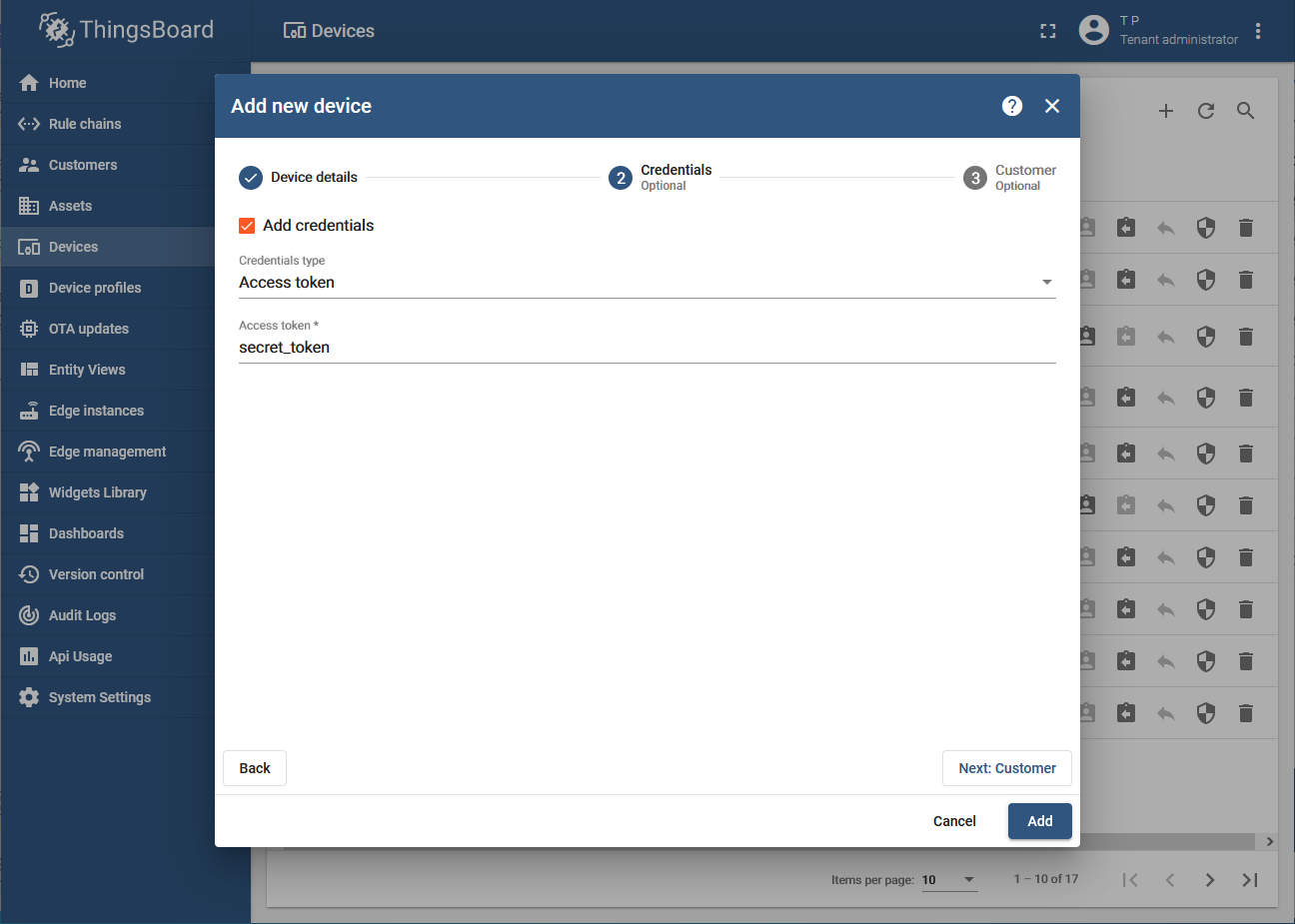
-
Click on Add (the third point, Customer, does not have to be configured).
You have now created the router in Thingsboard and generated an access token.
2.8. Setting up a connection from Node-RED to Thingsboard
In order to transmit the values read out in Node-RED to Thingsboard, an MQTT output must be added to the Node-RED flow.
-
Add a network node mqtt out in the workspace and double-click it to edit its properties.
-
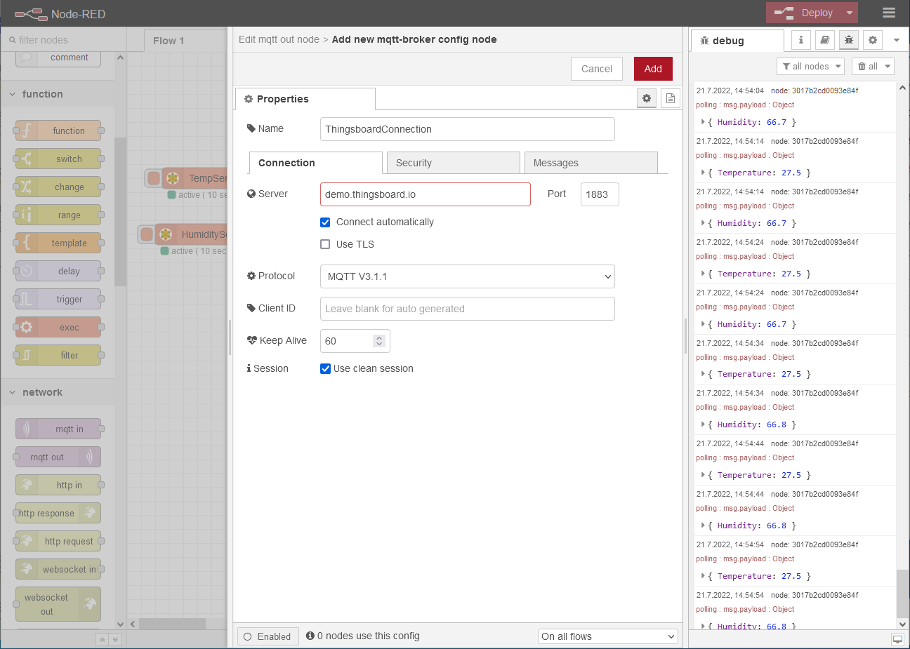
Click under Server on
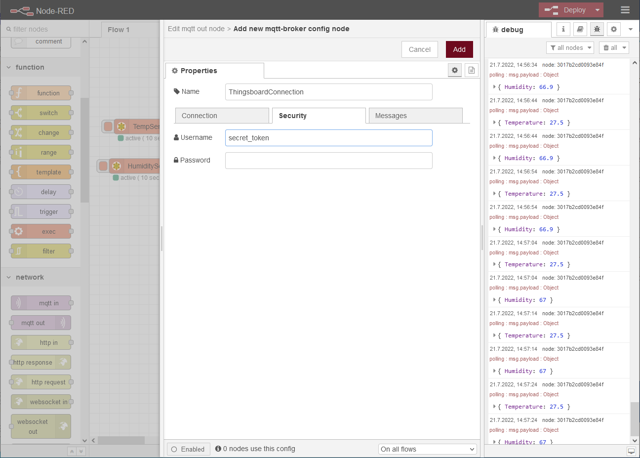
to configure the server connection on the Connection tab:-
Name: ThingsboardConnection
-
Server: demo.thingsboard.io
-
Port: 1883
-
Connect automatically:

-
Protocol: MQTT V3.1.1
-
Keep Alive: 60
-
Use clean session:
-
-
Change to the Security tab, enter the access token specified in Thingsboard under Username and leave the Password empty.
-
Click on Update .
-
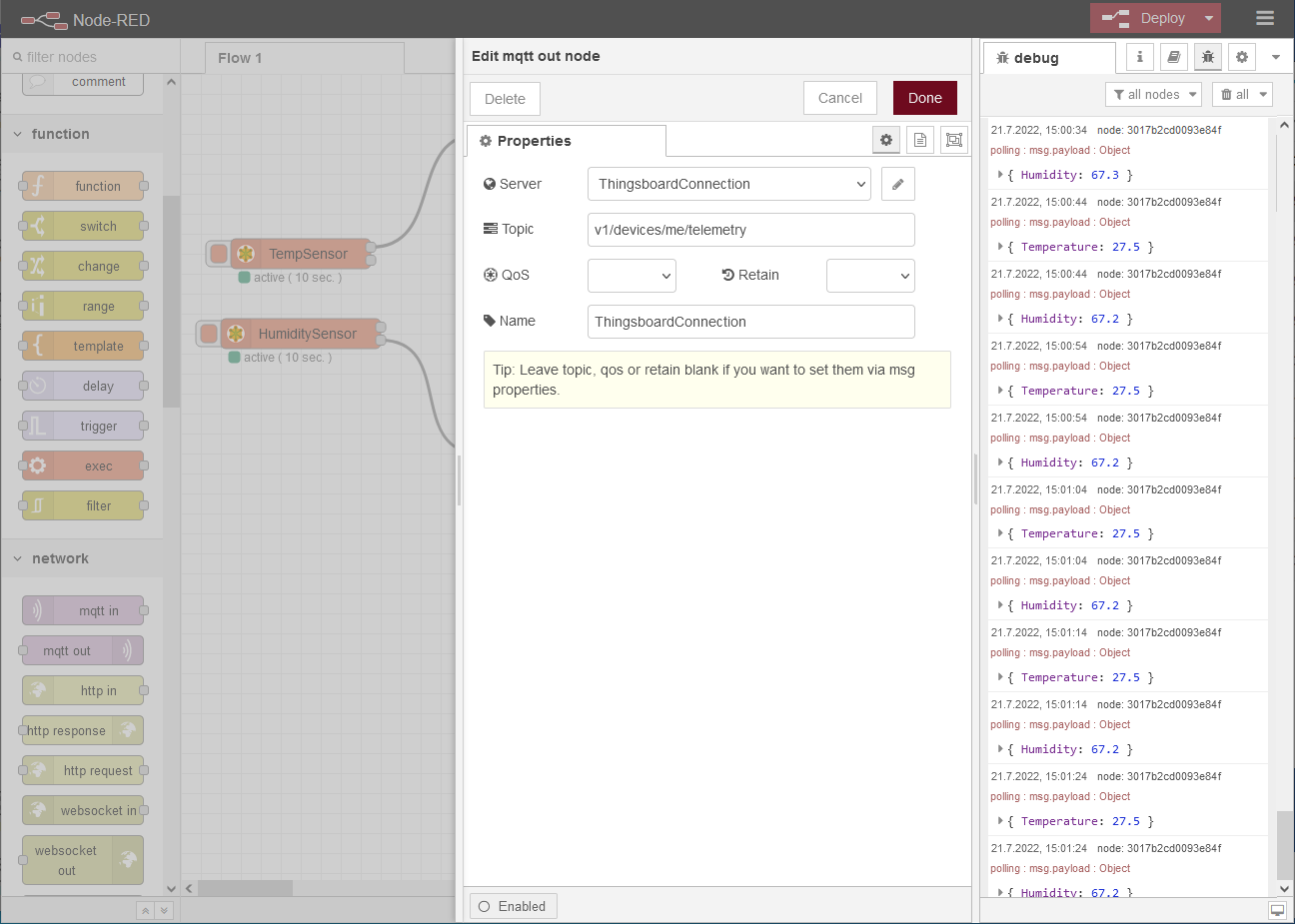
Enter v1/devices/me/telemetry as Topic and a descriptive Name.
-
Click on Done .
Connect the outputs of the two function nodes to the input of the MQTT output node.
-
Click on Deploy in the top right corner of the title bar to deploy the flow.
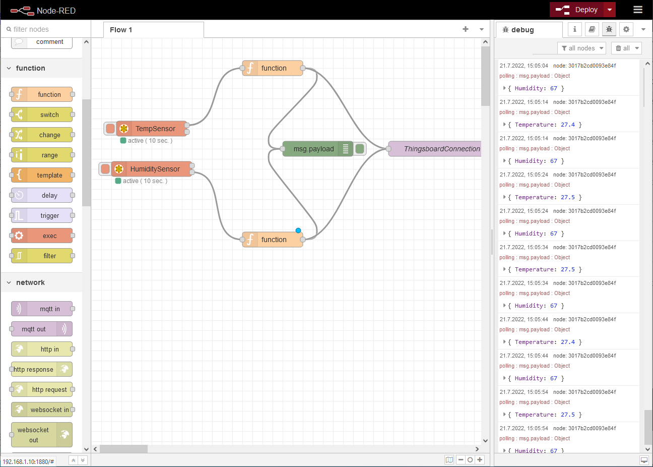
A green dot under the MQTT output node indicates the MQTT connection status.
3. Result testing
-
Click in Thingsboard into the row of your device and change to the Latest telemetry tab in the Device details.
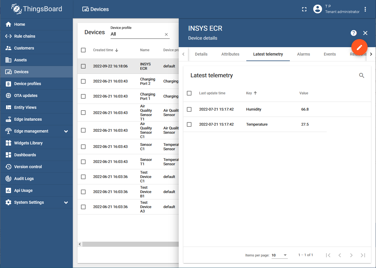
You see the latest values transmitted from Node-RED to Thingsboard now. You can now visualise these in Thingsboard using widgets.
4. FAQ
-
Why does the MQTT output node regularly lose its connection?
When the MQTT output node is deployed, it connects for a short time, disconnects and reconnects. Try Modbus - Flex - Getter or Modbus - Flex - Write instead. -
In which directory are the installed Node-RED modules located?
The nodes are installed under the user directory of Node-RED. This is ~/.node-red/ by default. This directory contains your Node-RED settings file, flow files and the package.json file that lists all installed modules. -
How can I save my flow with all the corresponding nodes?
Click on and select Export.
You can then download the desired flow in json format. -
Why do I get regular timeout or CRC errors when reading out the Modbus values?
If these errors occur more frequently, it may be because the serial port is being accessed from another source as well. Make sure that only the Node-RED container is accesses the serial port.