This Configuration Guide shows how to configure an LTE connection manually.
The description in this Configuration Guide follows a configuration in the new user interface (web interface) available from icom OS 5.5. Update your router to the latest version of icom OS for the required functionality of the new user interface. The description of this configuration in the classic web interface is available in this Configuration Guide.
Situation
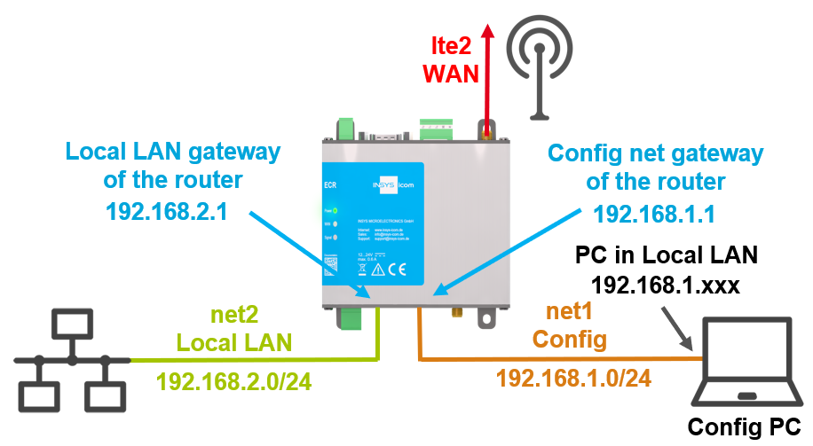
A local network is to be connected to the Internet via the LTE router manually.
Solution
The steps executed in the Startup wizard for configuring a cellular connection are carried out manually for this purpose.
It is prerequisite that the device has an LTE modem and a functional SIM card is inserted. This Configuration Guide assumes a device in default settings. In case of already configured devices or other network configuration requirements, the individual steps may need to be adapted.
|
|
The device can only be accessed via the first Ethernet socket in default settings. This avoids to bridge several networks accidentally on an already configured router when resetting to default settings. |
-
Open the user interface of the router in a browser: insys.icom [1]
-
Click To manual configuration on the splash screen under
 Manual configuration when the splash screen appears or enter your credentials if the router is no longer in factory settings.
 -
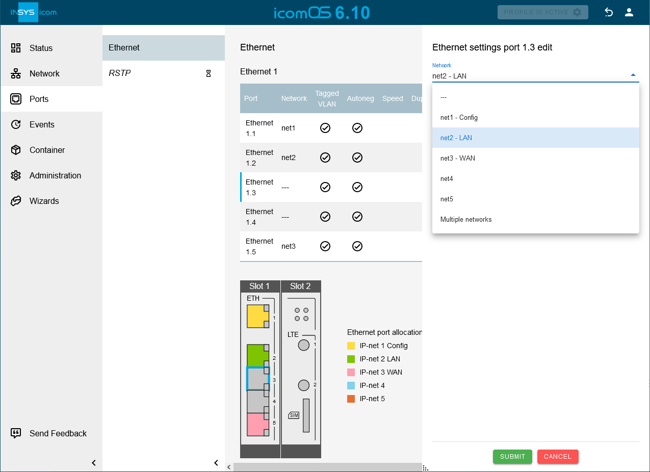
Open the
 Ports → Ethernet page and get an overview of the configuration of the Ethernet ports; adjust them with a click on
  in in the row of this port, if necessary. [2]
-
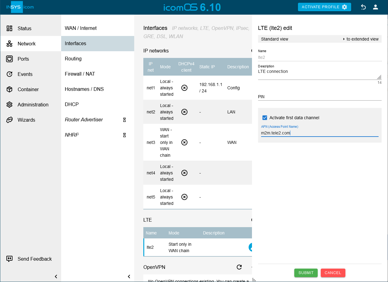
Open the
 Network → Interfaces page and get an overview of the configuration of the network interfaces; adjust them with a click on in in the row of this network interface, if necessary.
-
Click on the
Network → Interfaces page in the LTE ´table on in the row of the network lte2. [3]. -
Click on SUBMIT .
-
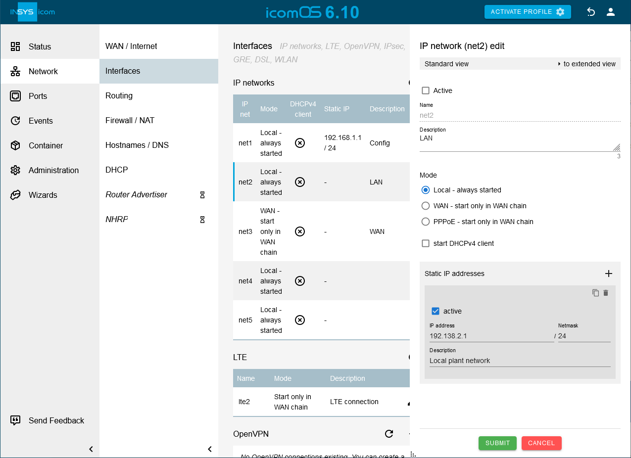
Click on the
Network → Interfaces page in the IP networks table on in the row of the network net2 and check the checkbox Active. -
Click on
 behind Static IP addresses and enter the IP address with Netmask the router is supposed to get in the LAN [7].
-
Click on SUBMIT .
-
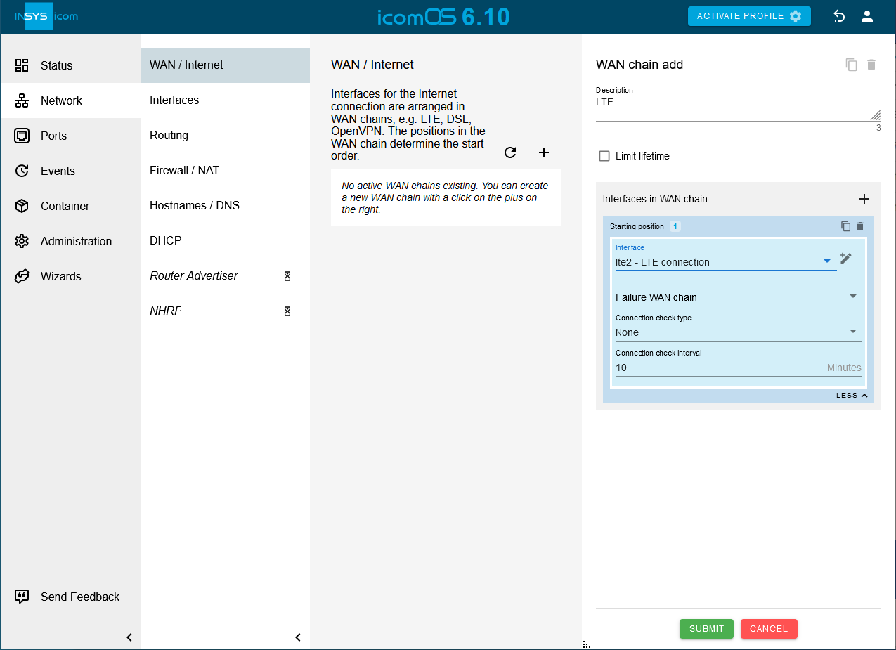
Click on icon: plus[] on the
Network → WAN / Internet page to add a WAN chain. [8] -
Click on
behind Interfaces in WAN chain to add an interface to this WAN chain and select the Interface lte2 [9].
-
Click on SUBMIT .
-
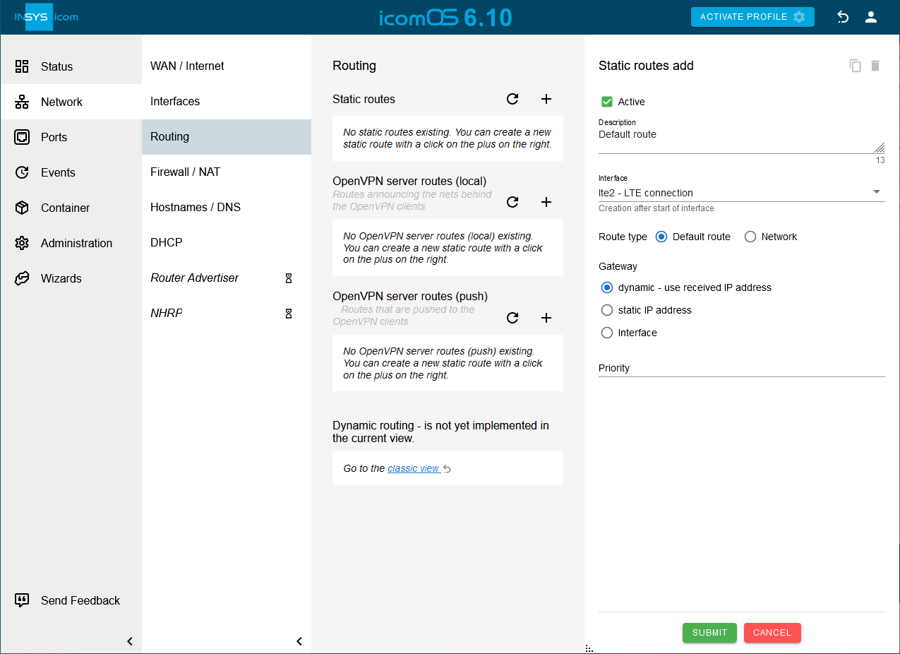
Click on
hinter Static routes on the Network → Routing page to add a static route [10]:-
Creation after start of Interface: lte2
-
Type of the route: Default route
-
Gateway: dynamic - use received IP address
-
-
Click on SUBMIT .
-
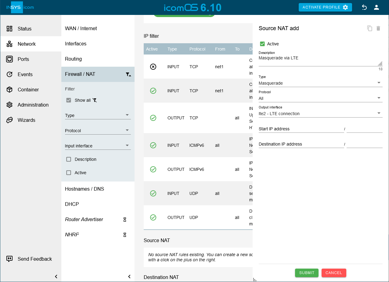
Click on
behind Source NAT on the Network → Firewall / NAT page to add a Source NAT rule [11]:-
Type: Masquerade
-
Protocol: All
-
Output interface: lte2

-
-
Click on SUBMIT .
-
If your router is still in default settings:
Open the Administration → User page and click on in the row of the user to configure the standard user and enter a User name and a Passwort.

-
Click on SUBMIT .
-
Activate the profile with a click on ACTIVATE PROFILE
 . [12]
Result testing
-
Open the
 Status → Dashboard page, check the settings of the local networks and observe the establishment of the LTE Connection and the WAN chain.

Troubleshooting
-
The status of the WAN chain and their interfaces is displayed on the
Status → Dashboard page.
If an interface does not achieve the online condition, its condition can also be examined on this page. -
If no network traffic is achieved, the tools integrated in the router can be used for debugging.
-
Network devices connected to the router cannot use the Internet connection. The reason can be that they have not entered the router as gateway and DNS server.
-
The IP filters can be deactivated for testing purposes. The router itself is also subject to the IP filters. If the router itself has to send packets, an OUTPUT rule is necessary for this. If the router itself has to receive packets, an INPUT rule is necessary for this. In order to be able to route IP packets, a FORWARD rule is necessary.
Back to the Configuration Guides for icom OS Smart Devices
Back to overview