Situation
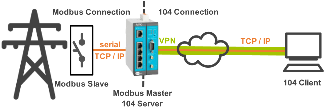
An autoreclosure device is mounted to a utility pole (substation) and monitors data measured at the pole. The autoreclosure device outputs the values to a TCP or serial interface using the Modbus protocol. The data needs to be transmitted to a network control center that accepts data on a TCP/IP interface using the IEC 60870–5–104 protocol. Data transmission takes place using an INSYS Smart Device (industrial router) using a secure VPN connection.
Solution
The icom Data Suite running on the INSYS Smart Device (industrial router) will act as a Modbus to 104 converter. The icom Data Suite acts as a Modbus master and reads out the individual values from the autoreclosure device that acts as a Modbus slave. The icom Data Suite will also act as a 104 server and map the Modbus values to 104 values. The 104 values can now be requested by the 104 client in the control center. They can also be sent by the 104 server using regularly triggered messages. Below example contains only one value, but can be extended accordingly to convert all values necessary for the application.
It is prerequisite that you have access to the web interface of the icom Data Suite.
It is also prerequisite that the INSYS Smart Device (industrial router) is properly configured to establish the VPN connection to the control center.
Configuring the Modbus Connection
-
In the Data points → Modbus menu, add a new device () and edit it ():
-
Description: Autoreclosure device
-
Type: select the connection type TCP (TCP/IP) or RTU (serial) depending on the Modbus connection
-
Enter address and port for TCP or the serial parameters for RTU [1]
-
Polling interval: 5
-
Slave address: enter the Modbus slave address of the autoreclosure device
-
Byte order: select as requested by the protocol
-
-
Click on Save settings.
-
In the Data points → Modbus menu in the Data points section, add a new data point () and edit it (): [2]
-
Click on Save settings.
Configuring the 104 Connection
-
In the Gateway → 104 server menu, add a new device () and edit it ():
-
Click on Save settings.
-
In the Gateway → 104 server menu in the Items section, add a new item () and edit it (): [8]
-
Click on Save settings.
-
In the Gateway → 104 server menu in the Items section, add a new item () and edit it (): [12]
-
Description: Message Switch ON/OFF
-
Type: Message
-
Mappings to send: check above added mapping mdbDp1 - Switch ON/OFF
-
-
Click on Save settings.
-
In the Events menu, add a new event () and edit it (): [13]
-
Click on Save settings.
-
Activate the profile ().
Troubleshooting
-
View the Status → Current values page to check whether the values from the autoreclosure device appear in the Modbus section if the control center does not receive these values. If the values are missing/incorrect there, check the configuration of the Modbus master in the icom Data Suite. If the correct values are displayed there, check the configuration of the 104 server in the icom Data Suite.
-
View the appropriate logs in the Status → Log view page (also of the router) to locate possible problems.
Resources
The following ASCII configuration can be taken over using copy & paste. It must be observed that the individual parameters need to be adapted to the own application. Correct numbering must be observed for numbered parameters. Moreover, it must be observed that no existing parameters with the same number will be overwritten. A proper functionality can only be ensured if the opened profile has been created from default settings before.
datapoints.modbus.device.add
datapoints.modbus.device[1].active=1
datapoints.modbus.device[1].description=Autoreclosure device
datapoints.modbus.device[1].type=tcp
datapoints.modbus.device[1].ip_address=192.168.101.13
datapoints.modbus.device[1].tcp_port=502
datapoints.modbus.device[1].serial_port=serial2.1
datapoints.modbus.device[1].serial_speed=115200
datapoints.modbus.device[1].serial_databits=8
datapoints.modbus.device[1].serial_parity=par_none
datapoints.modbus.device[1].serial_stopbits=1
datapoints.modbus.device[1].polling_interval=5
datapoints.modbus.device[1].slave_address=7
datapoints.modbus.device[1].endianess=big_abcd
datapoints.modbus.device[1].response_timeout=500
datapoints.modbus.device[1].byte_timeout=500
datapoints.modbus.device[1].read_delay=0

datapoints.modbus.device[1].datapoint.add
datapoints.modbus.device[1].datapoint[1].datapoint_active=1
datapoints.modbus.device[1].datapoint[1].datapoint_description=Switch ON/OFF
datapoints.modbus.device[1].datapoint[1].datapoint_type=holding_register
datapoints.modbus.device[1].datapoint[1].datapoint_register=7
datapoints.modbus.device[1].datapoint[1].datapoint_format=uint16

gateway.104server.gateway.add
gateway.104server.gateway[1].active=1
gateway.104server.gateway[1].description=Control center connection
gateway.104server.gateway[1].tcp_port=2404
gateway.104server.gateway[1].station_address=1

gateway.104server.gateway[1].item.add
gateway.104server.gateway[1].item[1].item_description=Switch ON/OFF
gateway.104server.gateway[1].item[1].item_active=1
gateway.104server.gateway[1].item[1].item_type=mapping
gateway.104server.gateway[1].item[1].map_datapoint=mdbDp1
gateway.104server.gateway[1].item[1].map_104type=doublep
gateway.104server.gateway[1].item[1].map_104ioa=527

gateway.104server.gateway[1].item.add
gateway.104server.gateway[1].item[2].item_description=Message Switch ON/OFF
gateway.104server.gateway[1].item[2].item_active=1
gateway.104server.gateway[1].item[2].item_type=message
gateway.104server.gateway[1].item[2].msg_maplist=104Item1
gateway.104server.gateway[1].item[2].msg_group=
gateway.104server.gateway[1].item[2].msg_timestamp=0

events.event.add
events.event[1].active=1
events.event[1].description=Send Switch ON/OFF to control center upon change
events.event[1].event_type=ev_analog
events.event[1].event_analog_datapoint=mdbDp1
events.event[1].event_analog_change=changed
events.event[1].action_type=act_message
events.event[1].action_message=104Item2
Back to the Configuration Guides for the icom Data Suite
Back to overview